
Wavelength Division Multiplexing/De-Multiplexing Optical Assembly for High Speed Parallel Long Distance Transmission

a technology of optical assembly and wavelength division, applied in the field of wavelength division multiplexing/demultiplexing optical assembly for high speed parallel long distance transmission, can solve the problems of existing communication system facing capacity and energy consumption, and conventional transmission techniques have failed to meet the demands of transmission capacity and transmission speed, and achieve low coupling efficiency, short transmission distance, and large insert loss

Inactive Publication Date: 2013-12-12
INNOLIGHT TECHNOLOGY (SUZHOU) LTD
View PDF6 Cites 20 Cited by
  • Summary
  • Abstract
  • Description
  • Claims
  • Application Information

AI Technical Summary

Benefits of technology

The present invention aims to overcome the shortcomings of existing wavelength division multiplexing / de-multiplexing optical assemblies for high speed parallel long distance transmission. The invention aims to resolve issues of large insert loss, low coupling efficiency, short transmission distance, low reliability, and difficulties for small outline package. In summary, the technical effect of the invention is to improve the performance of wavelength division multiplexing / de-multiplexing optical assemblies for high speed parallel long distance transmission.

Problems solved by technology

With the ever-increasing of the transmission capacity in the communication field, the conventional transmission techniques have failed to meet the demands for transmission capacity and transmission speed.
However, with the rapid increasing of the demand for communication bandwidth, the existing communication system faces the two challenges of capacity and energy consumption.

Method used


Image

  • Wavelength Division Multiplexing/De-Multiplexing Optical Assembly for High Speed Parallel Long Distance Transmission
  • Wavelength Division Multiplexing/De-Multiplexing Optical Assembly for High Speed Parallel Long Distance Transmission
  • Wavelength Division Multiplexing/De-Multiplexing Optical Assembly for High Speed Parallel Long Distance Transmission

Examples


Embodiment Construction

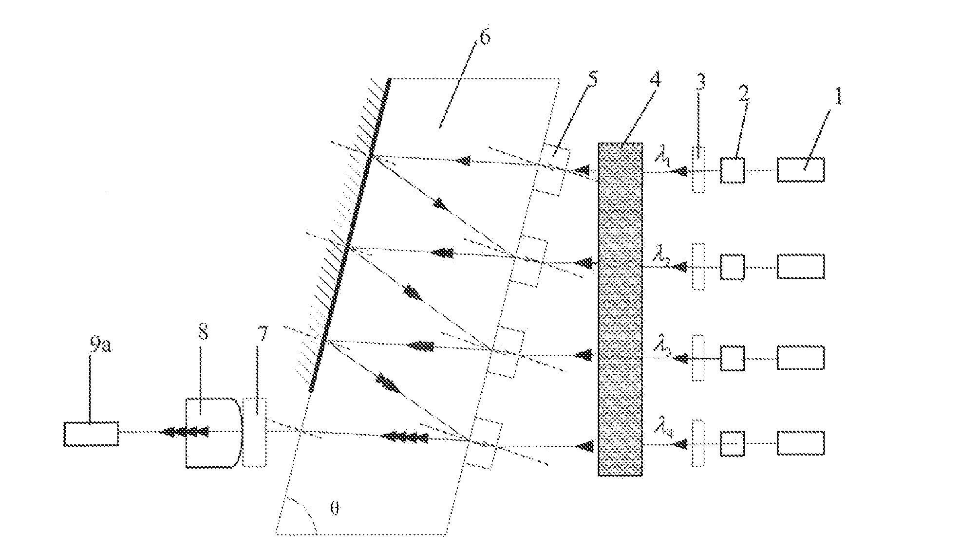
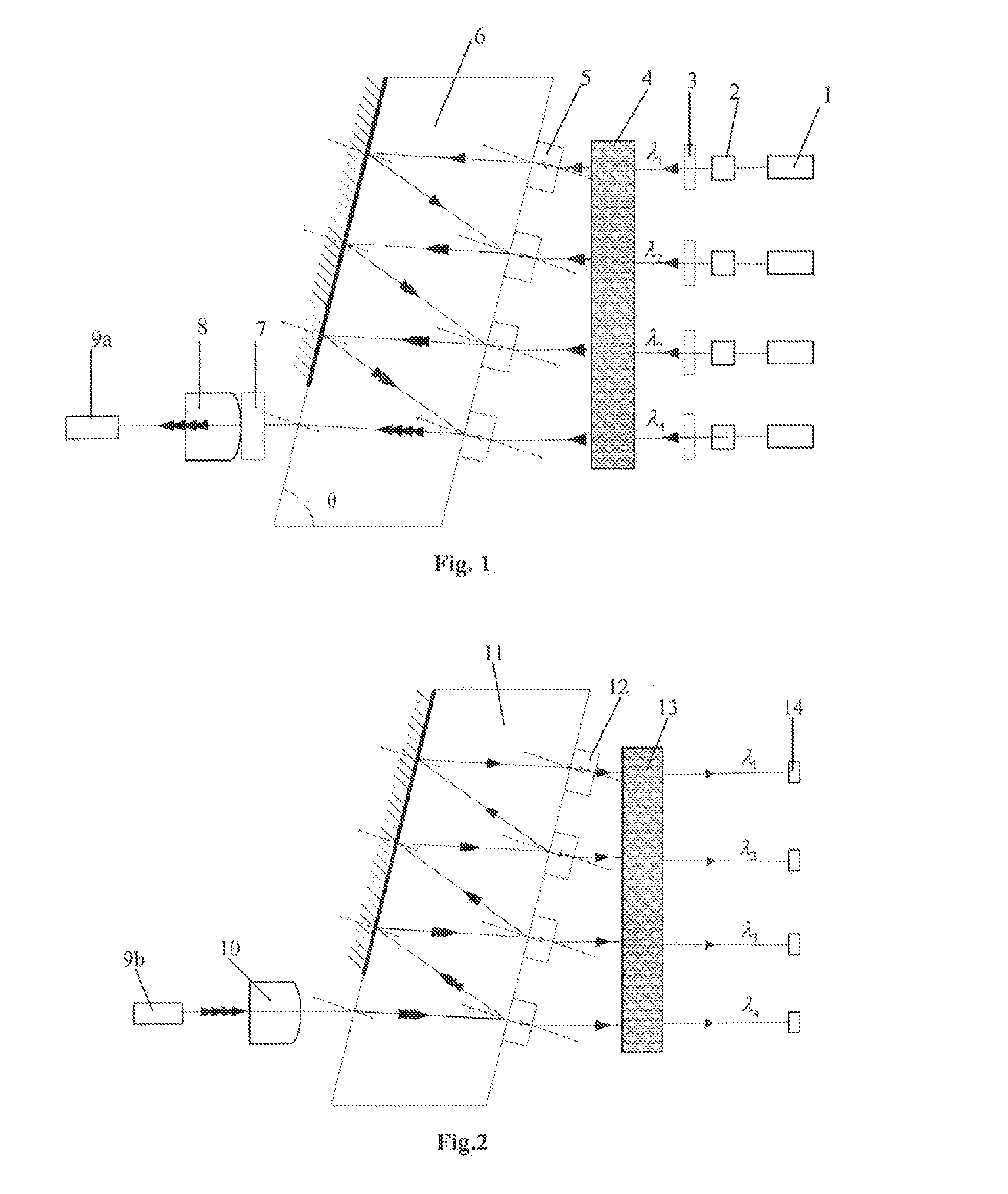
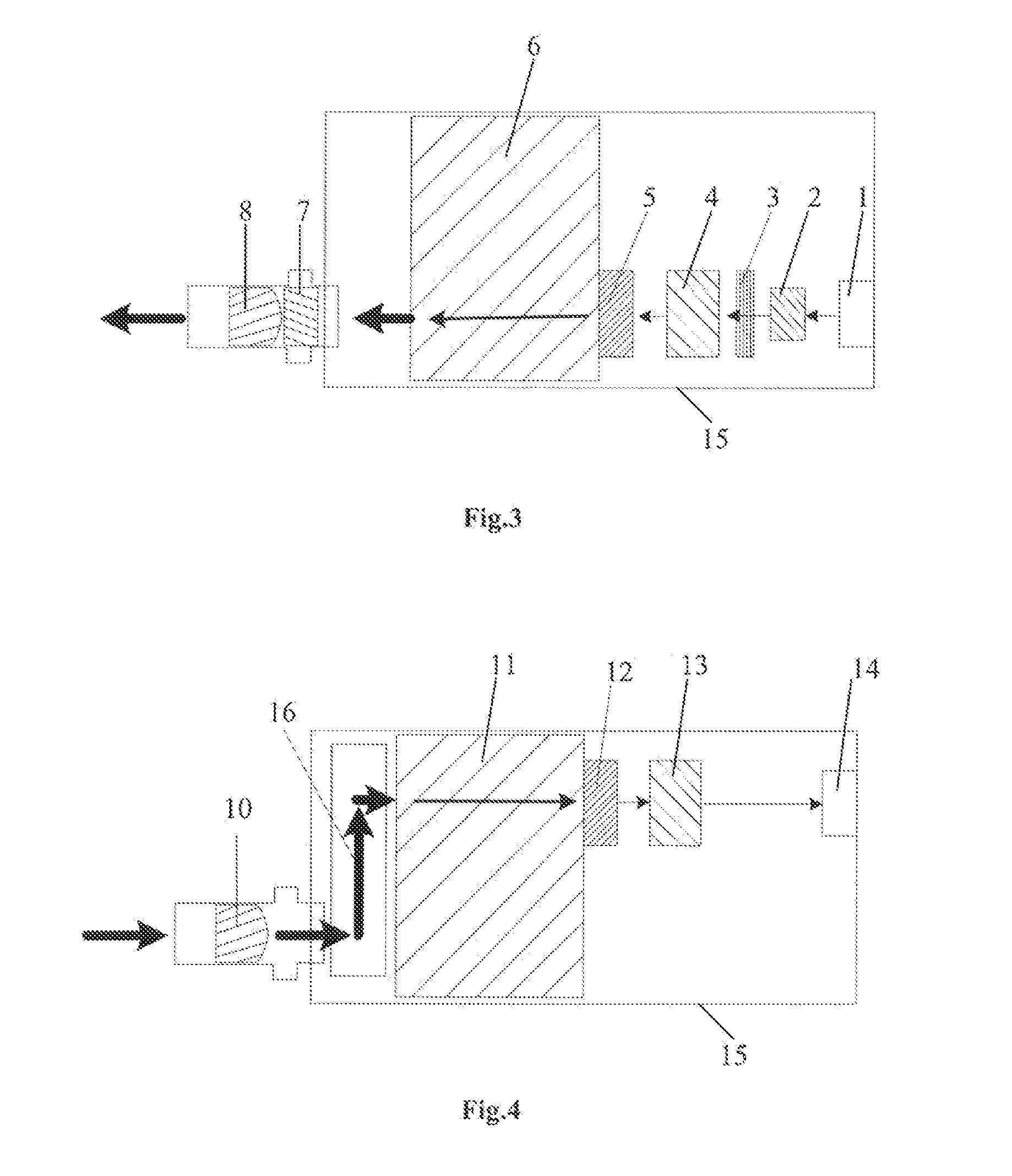
[0028]A wavelength division multiplexing / de-multiplexing optical assembly for high speed parallel long distance transmission comprises a transmitting terminal, a transmitting terminal optical lens group, a receiving terminal optical lens group and a receiving terminal disposed in turn. As shown in FIGS. 1 and 2, the transmitting terminal is a laser group 1 with a coarse wavelength division multiplexing wave length according to the provision of IEEE 802.3ba; the receiving terminal is a detector group 14 with a coarse wavelength division multiplexing wave length according to the provision of IEEE 802.3ba; the transmitting terminal optical lens group comprises a silicon lens group 2, an optical adjusting plate group 3, a lower layer silicon lens array 4, a lower layer filter group 5, a lower layer free space wavelength division multiplexer 6, an optical isolator 7 and a focusing lens 8; the receiving terminal optical lens group comprises a collimating lens 10, an upper layer free space...


PUM


Abstract

A wavelength division multiplexing / de-multiplexing optical assembly for high speed parallel long distance transmission, wherein, the output terminal of the laser group is provided with the silicon lens group, the optical adjusting plate group, the lower layer silicon lens array, the lower layer filter group, and the lower layer free space wavelength division multiplexer, the optical isolator, and the focusing lens arranged in turn; the output terminal of the focusing lens is coupled with an input optical fiber; an output optical fiber is coupled with the collimating lens; the output terminal of the collimating lens is coupled with a prism; the output terminal of the prism is provided with the upper layer free space wavelength division multiplexer, the upper layer filter group, the upper layer silicon lens array and the detector group arranged in turn. Thereby, multiplexing / de-multiplexing of optical signals is realized by use of filter groups.

Description

TECHNICAL FIELD[0001]The present application relates to a wavelength division multiplexing / de-multiplexing optical assembly for high speed parallel long distance transmission, which belongs to the technical field of optical transceiver modules in optical communication.BACKGROUND OF THE INVENTION[0002]With the ever-increasing of the transmission capacity in the communication field, the conventional transmission techniques have failed to meet the demands for transmission capacity and transmission speed. In the fields of data center application, as well as internet core node, education organization, search engine, large-scale web site, high performance computer, and so on, in order to avoid the insufficiency of the bandwidth resources of the central net, network operators and service providers are programming deployment of next generation internet protocol. The Institute of Electrical and Electronics Engineers (IEEE) has made the unified standard for 40 Gbps and 100 Gbps Ethernet under...

Claims


Application Information

Patent Timeline
IPC IPC(8): H04J14/02
CPCG02B6/29367H04J14/02
Inventor LI, WEILONGSUN, YUZHOUWANG, PANHUANG, PENGSHI, GAOHONGLIU, SHENG
Owner INNOLIGHT TECHNOLOGY (SUZHOU) LTD
Learn More