Tubular Stand Building and Racking System

a technology of building system and tubular stand, which is applied in the direction of drilling rods, drilling casings, drilling pipes, etc., can solve the problems of many things going wrong, and high cost of drilling operation

Active Publication Date: 2013-12-12
T & T ENG SERVICES
View PDF25 Cites 15 Cited by
  • Summary
  • Abstract
  • Description
  • Claims
  • Application Information

AI Technical Summary

Benefits of technology

[0029]An upper elevator is pivotally connected to the base frame for receiving a tubular in a vertical orientation from a lower elevator. The upper elevator has an upper gripper and a lower gripper. The upper gripper is vertically translatable along the length of the upper elevator. The upper and lower grippers are both capable of clamping onto the exterior of a drilling tubular and supporting the load of the tubular.

Problems solved by technology

Tripping the drill pipe is a very expensive and dangerous operation for a drilling rig.
Most injuries that occur on a drilling rig are related to tripping the pipe.
Additionally, the wellbore is making no progress while the pipe is being tripped, so it is downtime that is undesirable.
Drill bits that fail prematurely can add significant cost to a drilling operation.
Needless to say, many things can and do go wrong in this process, which is why tripping pipe and pipe racking is a primary safety issue in a drilling operation.
Such systems are very large and very expensive, and are not suitable for use on a traditional land-based drilling rig.
This cantilever mast mounted system has a relatively low vertical load limit, and therefore requires assistance of the top drive when handling larger diameter collars and heavy weight collars.
The movement of the pipe with this system is somewhat unpredictable and requires significant experience to control.
It grasps the pipe from above the center of gravity of the tubular and fails to control the hostile movement of the pipe stand sufficiently to allow for safe handling of the stands or for timely movement without the intervention of drilling crew members.
In particular, the system is not capable of aligning the lower free end of the drill stand accurately for stabbing into the drill string in the wellbore.
As a result of these and other deficiencies, the system has had limited acceptance in the drilling industry.
A primary difficulty in mechanizing pipe stand racking is the hostile movement of the pipe that is generated by stored energy in the stand, misaligned vertical movement, and the lateral acceleration and resultant bending and oscillation of the pipe, which combine to generate hostile and often unpredictable movements of the pipe, making it hard to position, and extremely difficult to stab.
A conflicting difficulty in mechanizing pipe stand racking is the need to move the pipe with sufficient rapidity so that cost savings are obtained over the cost of manual manipulation by an experienced drilling crew.
Another primary obstacle in mechanizing pipe stand racking is the prediction and controlled management of the pipe stand movement sufficient to permit the precise alignment required for stabbing the pipe to a first target location on the drill floor and to a second target location within the fingers of the racking board.
An even greater obstacle in mechanizing pipe stand racking is the prediction and controlled management of the pipe stand movement sufficient to achieve the precise alignment required for stabbing the tool joint of the tubular held by the racking mechanism into the receiving tubular tool joint connection extending above the wellbore and drill floor.
Another obstacle to land-based mechanizing pipe stand racking is the lack of drilling floor space to accommodate a railed system like those that can be used on large offshore drilling rigs.
Another obstacle to mechanizing pipe stand racking is the several structural constraints that are presented by the thousands of existing conventional drilling rigs, where the need to retrofit is constrained to available space and structure.
Another obstacle to mechanizing pipe stand racking is the need to provide a reliable mechanized solution that is also affordable for retrofit to a conventional drilling rig.
Still another obstacle to mechanizing pipe stand racking is the need to grip and lift pipe stands within the narrow confines of parallel rows of pipe stands in a conventional rack.
Thus, technological and economic barriers have prevented the development of a pipe racking system capable of achieving these goals.
Conventional prior art drilling rig configurations remain manpower and equipment intensive to trip pipe and rack pipe when tripping.
Alternative designs have failed to meet the economic and reliability requirements necessary to achieve commercial application.
In particular, prior art designs fail to control the natural attenuation of the pipe and fail to position the pipe with sufficient rapidity and accuracy.

Method used


Image

  • Tubular Stand Building and Racking System
  • Tubular Stand Building and Racking System
  • Tubular Stand Building and Racking System

Examples


Embodiment Construction

[0064]The following description is presented to enable any person skilled in the art to make and use the invention, and is provided in the context of a particular application and its requirements. Various modifications to the disclosed embodiments will be readily apparent to those skilled in the art, and the general principles defined herein may be applied to other embodiments and applications without departing from the spirit and scope of the present invention. Thus, the present invention is not intended to be limited to the embodiments shown, but is to be accorded the widest scope consistent with the principles and features disclosed herein.

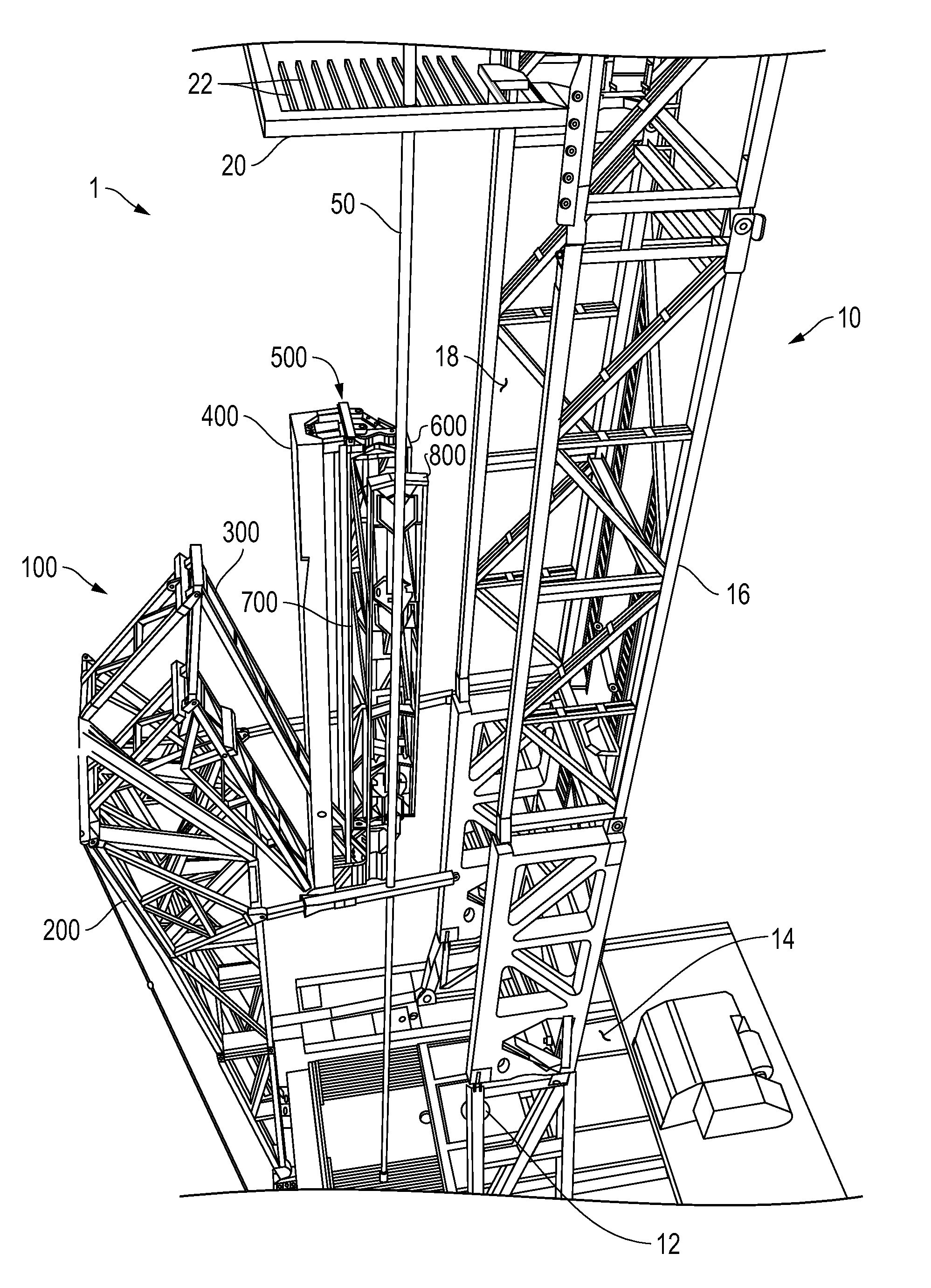
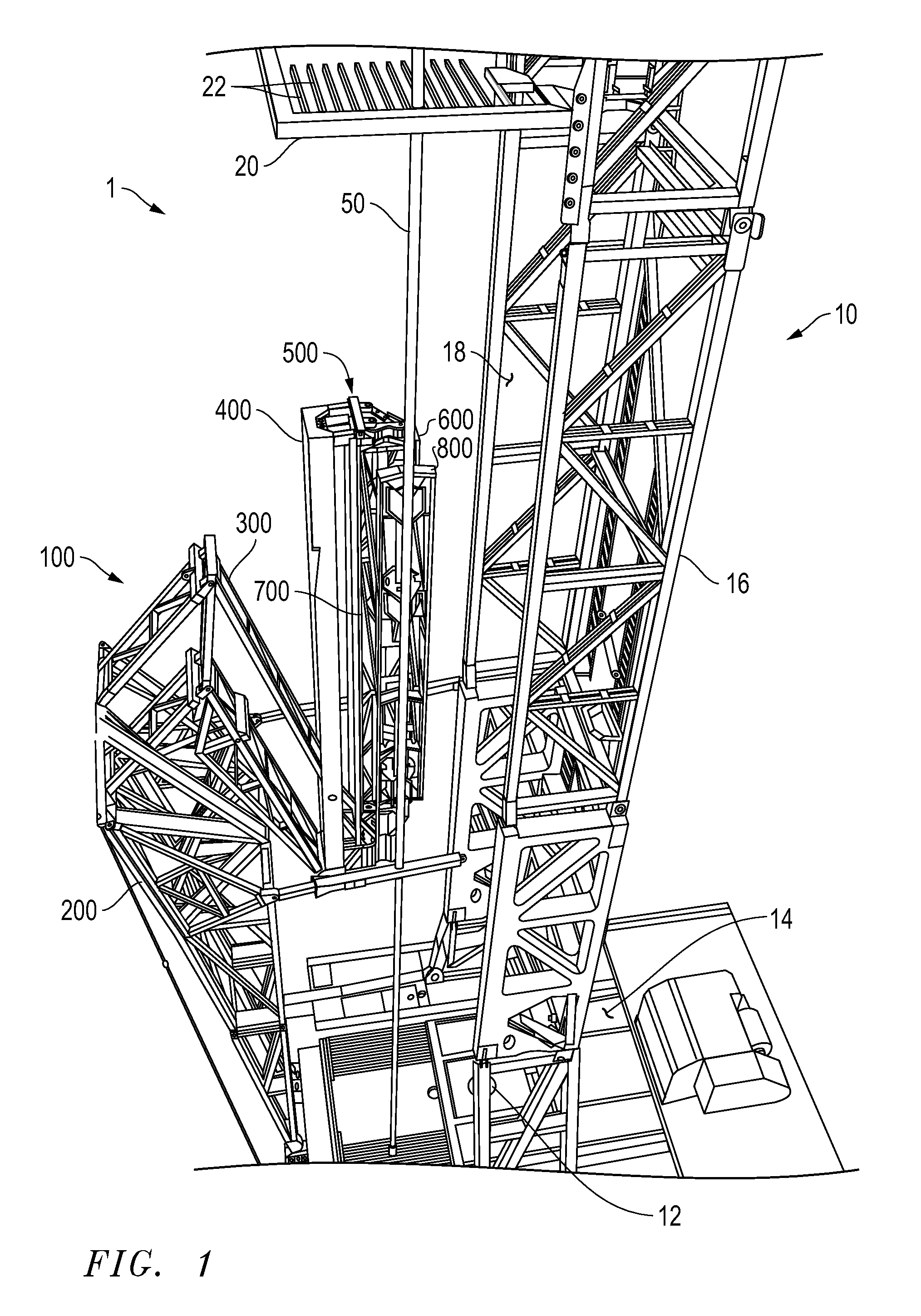
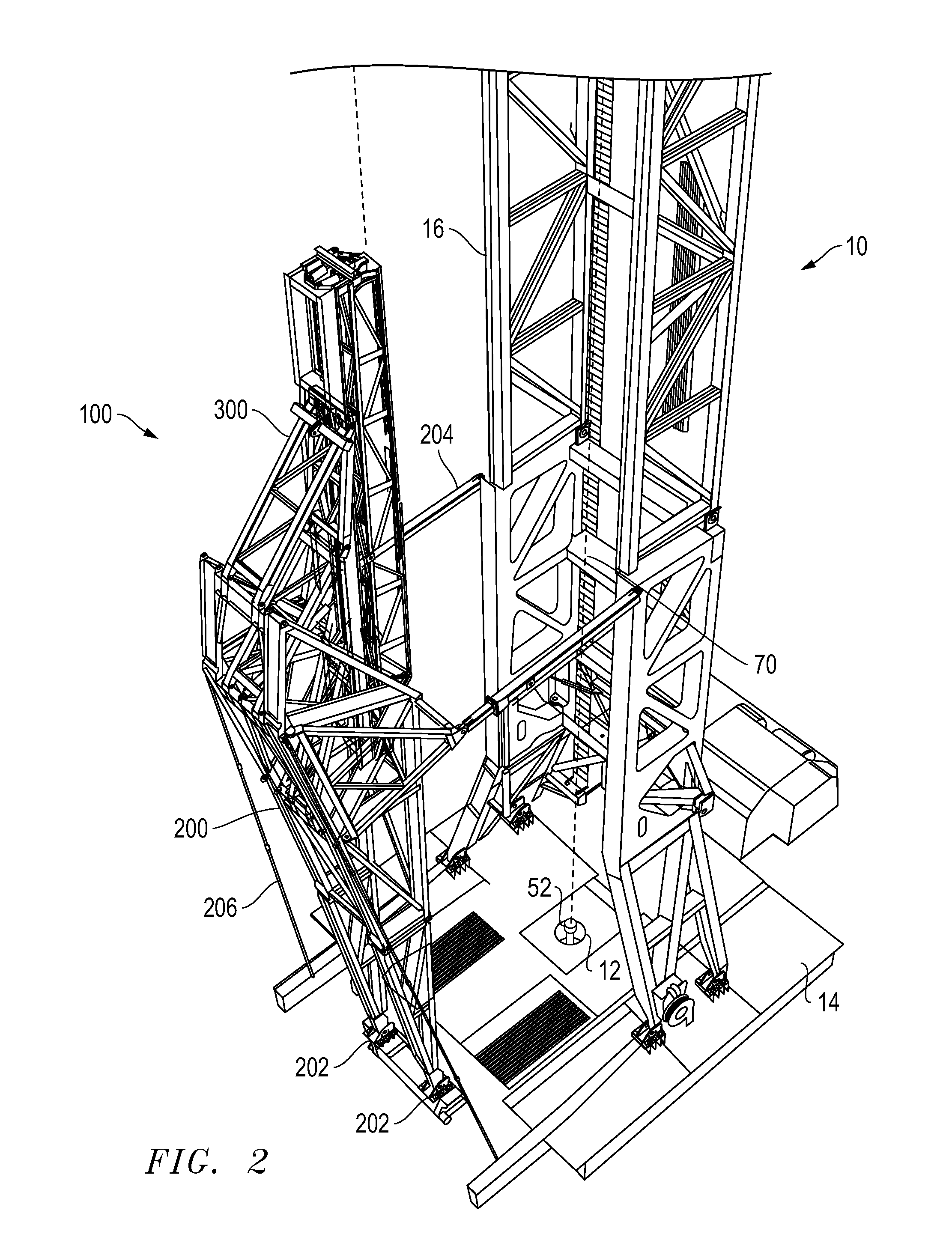
[0065]FIG. 1 is an isometric view of a racking mechanism 100 including features of the automatic stand building system 1. As it pertains to the present invention, racking mechanism 100 is one component of automatic stand building system 1. Although significant detail is provided below for racking mechanism 100, it will be appreciated that many ...


PUM


Abstract

The present invention provides a rapid rig-up and rig-down pipe stand building and racking system that is capable of being retrofit to an existing drilling rig. In particular, the invention relates to a horizontal to vertical pipe delivery machine that is mountable to a drilling rig. The horizontal to vertical machine delivers sections of pipe to a pair of drilling rig mounted elevators. The elevators receive and vertically translate the sections of pipe. A power tong may be used to make connections between the sections of pipe to form a pipe stand, and may also break the connections of the pipe stand. A drill floor mounted pipe racking system receives the connected drill pipe from the elevators. A pipe racking system that may be used in conjunction with the stand building system is capable of controlled, rapid, and precise movement of multiple connected sections of pipe.

Description

TECHNICAL FIELD OF INVENTION[0001]The present invention relates to a new apparatus and method for use in subterranean exploration. The present invention provides a rapid rig-up and rig-down pipe stand building system that is capable of being retrofit to an existing drilling rig. In particular, the invention relates to a drilling rig mountable horizontal to vertical pipe delivery machine. The pipe delivery machine delivers pipe to a pair of drilling rig mounted elevators. A drill floor mounted pipe racking system receives the drill pipe from the elevators. The pipe racking system is capable of controlled, rapid, and precise movement of multiple connected sections of pipe. The elevator system is mounted in between for make-up of the single pipe joints into a pipe stand.BACKGROUND OF THE INVENTION[0002]In the exploration of oil, gas and geothermal energy, drilling operations are used to create boreholes, or wells, in the earth. Subterranean drilling necessarily involves the movement of...

Claims


Application Information

Patent Timeline
Patent Type & Authority Applications(United States)
IPC IPC(8): E21B19/14
CPCE21B19/14E21B19/087E21B19/155E21B19/20
Inventor ORGERON, KEITH J.
Owner T & T ENG SERVICES
Why Eureka
Try Eureka