This helps you quickly interpret patents by identifying the three key elements:
Problems solved by technology
Method used
Benefits of technology
Benefits of technology
The present invention aims to improve the lighting efficiency and optical quality of surface light sources and display devices. It does this by reducing the heat generated by the LED chip and avoiding that the phosphor become overheated. This results in increased efficiency and better color reproduction, improving the overall quality of the surface light source and display device.
Problems solved by technology
The luminance of a phosphor is reduced with increasing temperature; the current disposition of the phosphor is close to the LED chip such that the heat generated by the LED chip will affect the luminance of the phosphor, reducing the lighting efficiency of the phosphor.
On the other hand, the luminance of the phosphor affect the light color of the LED and increase color shift of the LED so as to decrease the optical efficiency and optical quality of the surface light source.
Method used
Image
Click on the blue label to locate the original text in one second.
Reading with bidirectional positioning of images and text.
Examples
first embodiment
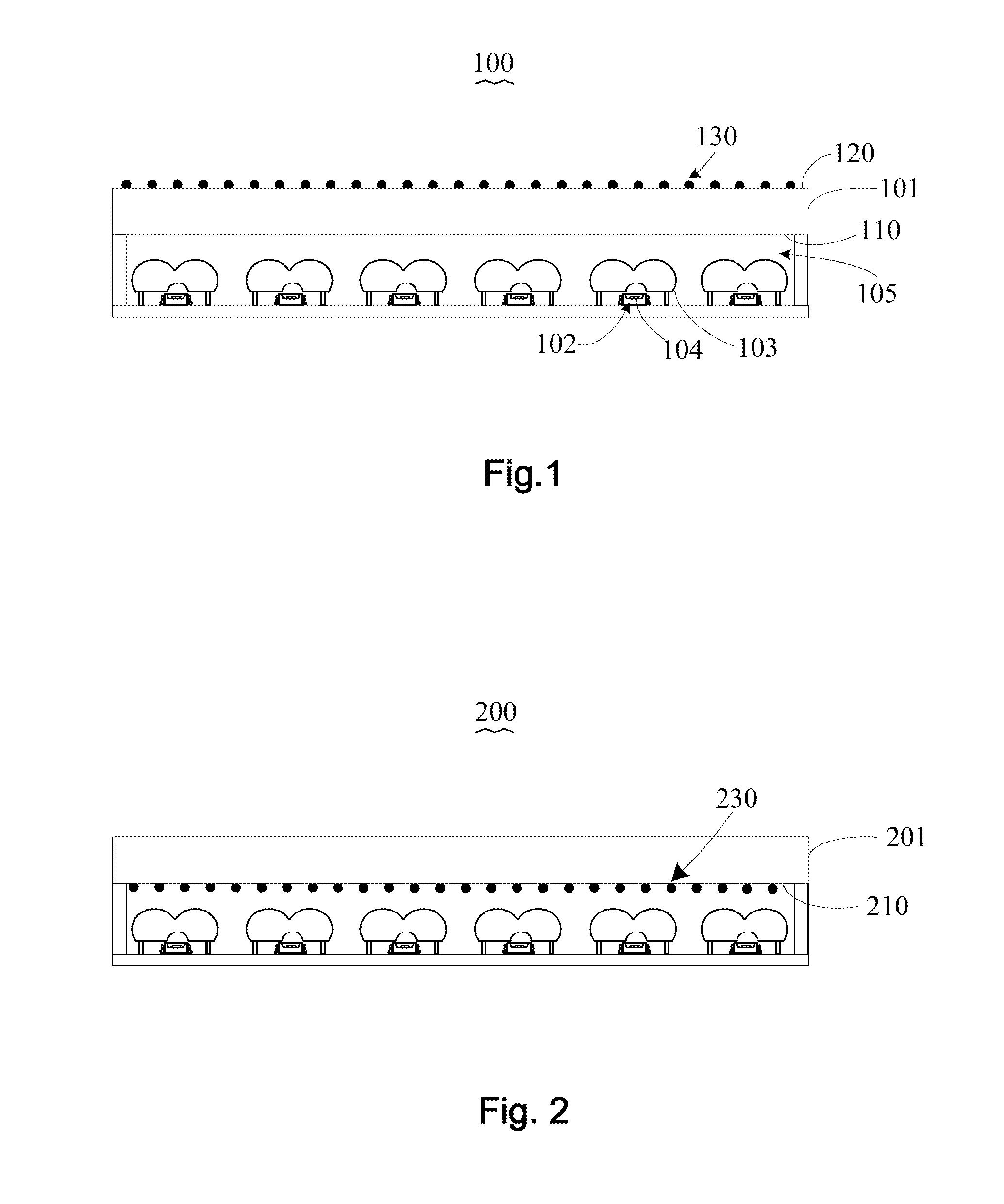
[0041]Please refer to FIG. 1, FIG. 1 is a schematic drawing of a surface light source of the present invention. As shown in FIG. 1, the surface light source 100 of the present invention includes a diffusion plate 101, an LED light source 102, and a condenser device 103.
[0042]Wherein, the LED light source 102 includes an LED chip 104, and the diffusion plate 101 is disposed at light emitting direction of the LED light source 102, and a plurality of phosphors 130 are disposed on the light diffusion plate 101, and the diffusion plate 101 and the LED light source 102 are separated to form a heat dissipation space 105, as shown in FIG. 1. The condenser device 103 is disposed between the LED light source 102 and the diffusion plate 101 to converge the lights from the LED light source 102 to the diffusion plate 101.
[0043]In this embodiment, the diffusion plate 101 includes a light incident surface 110 and a light emitting surface 120. The light incident surface 110 and the light emitting s...
second embodiment
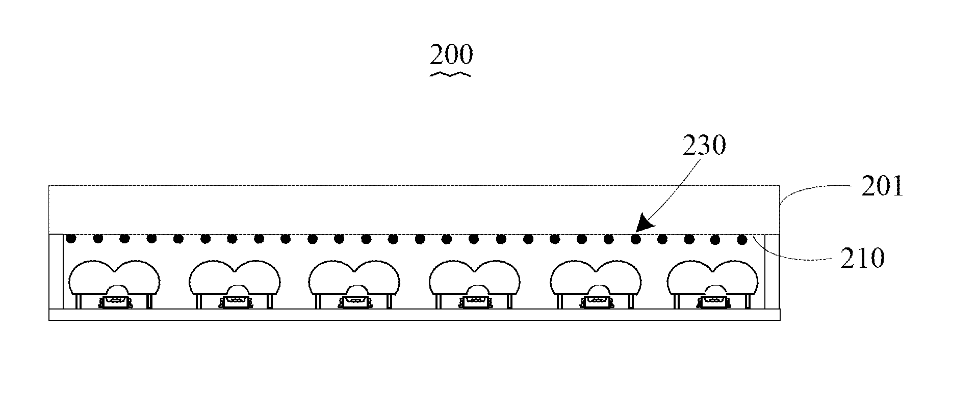
[0053]Please refer to FIG. 2, FIG. 2 is a schematic drawing of a surface light source of the present invention. Comparing with the embodiment shown in FIG. 1, the main difference of the backlight system 200 is that the positions of the plurality of phosphor are different, wherein, a plurality of phosphors 230 are disposed at a light incident surface 210 of a diffusion plate 201.
third embodiment
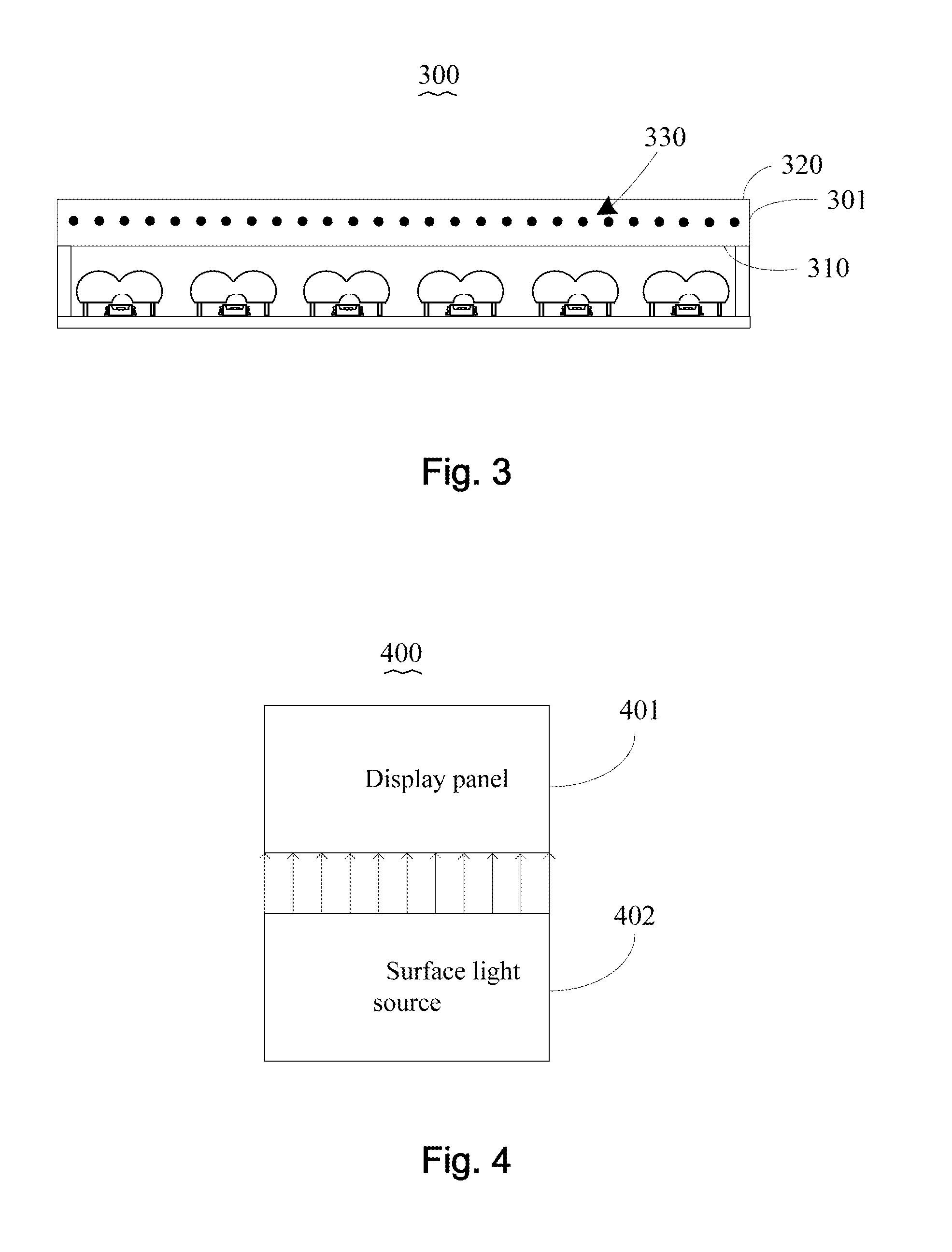
[0054]Please refer to FIG. 3, FIG. 3 is a schematic drawing of a surface light source of the present invention. Comparing with the embodiment shown in the FIG. 1, the main difference of backlight system 300 is that the positions of the plurality of phosphors are different, wherein, a plurality of phosphors 330 are disposed between a light incident surface 310 and a light emitting surface 320 of a diffusion plate 301.
[0055]Please refer to FIG. 4, FIG. 4 is a schematic drawing of a display device of the present invention. As shown in FIG. 4, the display device of the present invention 400 comprises a display panel 401 and a surface light source 402, wherein, the surface light source 402 is to provide the lights for the display panel 401.
[0056]In this embodiment, the surface light source 402 is the surface light source 100, the surface light source 200, or the surface light source 300 shown in FIG. 1 to FIG. 3 respectively. The specific structures and operation principles could refer t...
PUM
Abstract
The present invention provide a surface light source, wherein, the surface light source comprises a LED light source, the diffusion plate and condenser plant. The diffusion plate has a phosphor, and the diffusion plate and the LED light source are disposed separately to form a heat dissipation space. The condenser device disposes between the LED light source and the diffuser plate for converging the light emitted from LED light source to the diffusion plate.Therefore, in the present invention, the phosphor is far away from the LED light source to avoid the heat generated by the LED chip directly transmitting to the phosphor such that the heat received by the phosphor is reduced, decreasing the temperature of the phosphor, and avoiding that the lighting efficiency of the phosphor become lower due to high temperature, and improve the color shill problem of the LED light source with manufacturing processes so as to increase the optical efficiency and optical quality of the surface light source and the display device using the same.
Description
BACKGROUND OF THE INVENTION[0001]1. Field of the Invention[0002]The present invention relates to display technology, and more particularly to a surface light source and a display device.[0003]2. Description of Related Art[0004]Currently, the surface light source of the display device usually uses a SMD (Surface Mounted Devices) type LED as a light source. Wherein, the SMD-type LED includes an LED chip and a plurality of phosphors, and the plurality of phosphors directly coat on the LED chip or uniformly distribute in the packaging materials of the LED itself[0005]The luminance of a phosphor is reduced with increasing temperature; the current disposition of the phosphor is close to the LED chip such that the heat generated by the LED chip will affect the luminance of the phosphor, reducing the lighting efficiency of the phosphor. On the other hand, the luminance of the phosphor affect the light color of the LED and increase color shift of the LED so as to decrease the optical efficie...
Claims
Application Information
Patent Timeline
Application Date:The date an application was filed.
Publication Date:The date a patent or application was officially published.
First Publication Date:The earliest publication date of a patent with the same application number.
Issue Date:Publication date of the patent grant document.
PCT Entry Date:The Entry date of PCT National Phase.
Estimated Expiry Date:The statutory expiry date of a patent right according to the Patent Law, and it is the longest term of protection that the patent right can achieve without the termination of the patent right due to other reasons(Term extension factor has been taken into account ).
Invalid Date:Actual expiry date is based on effective date or publication date of legal transaction data of invalid patent.

