Cutting insert

Active Publication Date: 2013-12-19
KORLOY
View PDF11 Cites 21 Cited by
  • Summary
  • Abstract
  • Description
  • Claims
  • Application Information

AI Technical Summary

Benefits of technology

[0017]According to the embodiments, since one or more lateral relief surfaces from among the plurality of lateral relief surfaces are formed into three stages of a first positive surface, a negative surface and a second positive surface i

Problems solved by technology

Since the surface of the workpiece and the cutting edge forms negative rake angle therebetween i

Method used


Image

  • Cutting insert
  • Cutting insert
  • Cutting insert

Examples


Embodiment Construction

[0031]Certain exemplary embodiments of the present invention will now be described in greater detail with reference to the accompanying drawings.

[0032]In the following description, same drawing reference numerals are used for the same elements even in different drawings. The matters defined in the description, such as detailed construction and elements, are provided to assist in a comprehensive understanding of the invention. Thus, it is apparent that the exemplary embodiments of the present invention can be carried out without those specifically defined matters. Also, well-known functions or constructions are not described in detail since they would obscure the invention with unnecessary detail.

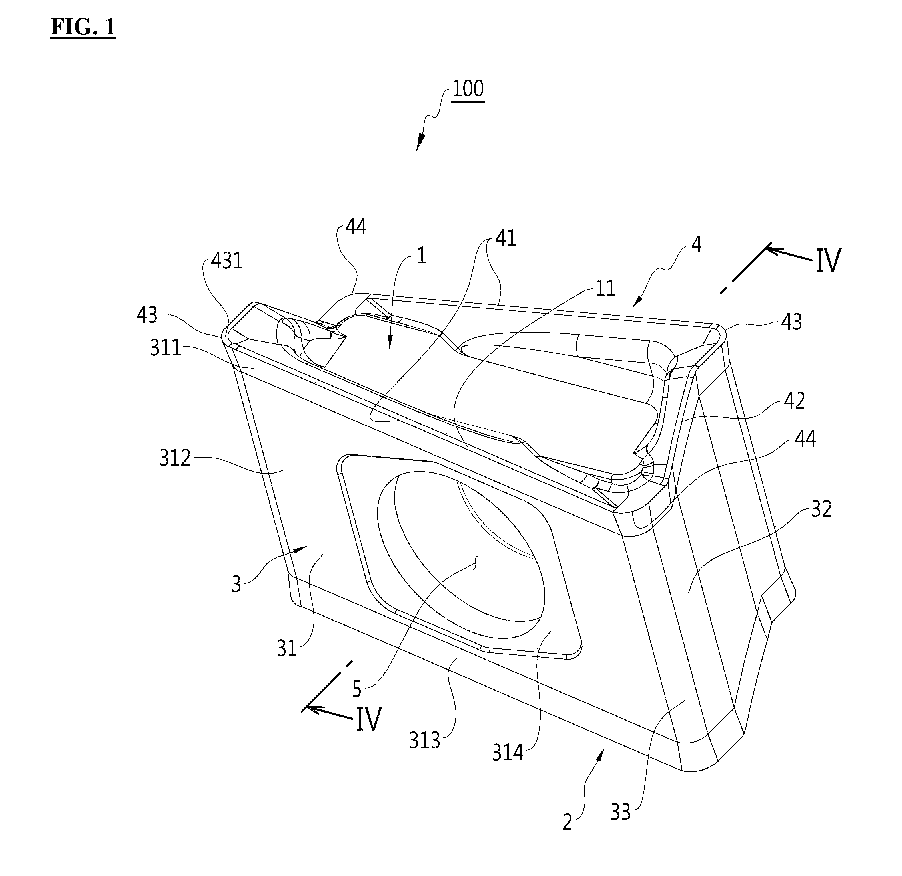
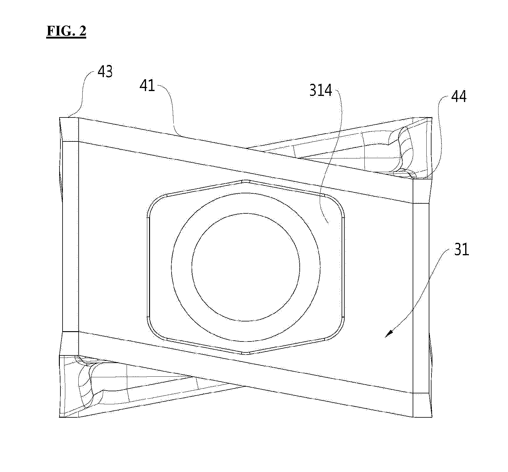
[0033]A double-sided cutting insert 100 according to an embodiment will be explained below with reference to the accompanying drawings.

[0034]FIG. 1 is a perspective view of a double-sided cutting insert according to an embodiment, FIG. 2 is a side view of the double-sided cutting insert of F...


PUM

PropertyMeasurementUnit
Angleaaaaaaaaaa
Angleaaaaaaaaaa

Abstract

A cutting insert, and more particularly, an improved double-sided cutting insert is provided, which provides improved machinability obtained due to increased rake angle, without compromising coupling state. The double-sided cutting insert includes a top surface, a bottom surface, a plurality of lateral relief surfaces connecting the top and bottom surfaces, and a cutting edge formed by the top and bottom surfaces and the plurality of lateral relief surfaces, in which one or more lateral relief surfaces of the plurality of lateral relief surfaces are formed into three stages in sequence which are a first positive surface, a negative surface and a second positive surface in a direction from the top surface to the bottom surface.

Description

CROSS-REFERENCE TO RELATED APPLICATIONS[0001]This application claims priority from Korean Patent Application No. 10-2012-0063600, filed on Jun. 14, 2012, in the Korean Intellectual Property Office, the disclosure of which is incorporated herein by reference in its entirety.BACKGROUND OF THE INVENTION[0002]1. Field of the Invention[0003]The present invention relates to a double-sided cutting insert.[0004]2. Description of the Related Art[0005]Generally, a cutting tool is used for cutting irons, non-iron metals, or non-metallic materials, and is mounted on a machine tool to process a workpiece into a desired shape. Such machine tool includes a cutting insert having a cutting edge, and a tool holder to secure the cutting insert in place.[0006]By way of example, a milling cutter uses the cutting insert in which length of the cutting edge contributing to cutting has to increase to enable deeper cuts in the orthogonal or lateral cutting. This leads into increased resistance on the overall...

Claims


Application Information

Patent Timeline
IPC IPC(8): B23B27/16
CPCB23C2200/286B23C5/06B23C2200/0494B23C2200/085B23C2200/367Y10T407/1924Y10T407/23B23C5/202B23C2200/287
Inventor NAM, KI-CHANLEE, SANG-YONGSUNG, WOOK-JUNGPARK, DONG-BOKLEE, JONG-CHAN
Owner KORLOY
Why Eureka
Try Eureka