Automatic Inspection of a Lightning Protection System on a Wind Turbine

a technology for lightning protection and wind turbines, applied in the field of automatic inspection of lightning protection systems on wind turbines, can solve the problems of mechanical components, wind turbine components damaged, and significant damage to components,

Inactive Publication Date: 2013-12-19
CLIPPER WINDPOWER INC
View PDF3 Cites 34 Cited by
  • Summary
  • Abstract
  • Description
  • Claims
  • Application Information

AI Technical Summary

Problems solved by technology

Wind turbines are frequently struck by lightning, which can cause significant damage to components of the wind turbine.
Not only can the various electrical components and electronics within the wind turbine be damaged by the high voltage and large currents of a lightning strike, mechanical components, such as pitch bearings, can also be damaged.
Lightning current passing through a bearing can cause localized pitting and other damage due to the high current and heat.
The resistance can increase over time due to wear on certain components in the conductive pathway.
Over time, the brushes can wear and the resistance through the brushes may increase.
This technician time comes at a high cost.
Second, the results of the inspection are also prone to errors resulting from human intervention.
Third, the cost of deploying the lift truck can be substantial.
Fourth, the wind turbine must be offline for the length of time necessary to complete the inspection, and this downtime results in a loss of power production and therefore profits for the wind turbine owner.
Thus, the overall cost of performing a manual inspection of a lightning protection system on a wind turbine can be very high.

Method used


Image

  • Automatic Inspection of a Lightning Protection System on a Wind Turbine
  • Automatic Inspection of a Lightning Protection System on a Wind Turbine
  • Automatic Inspection of a Lightning Protection System on a Wind Turbine

Examples


Embodiment Construction

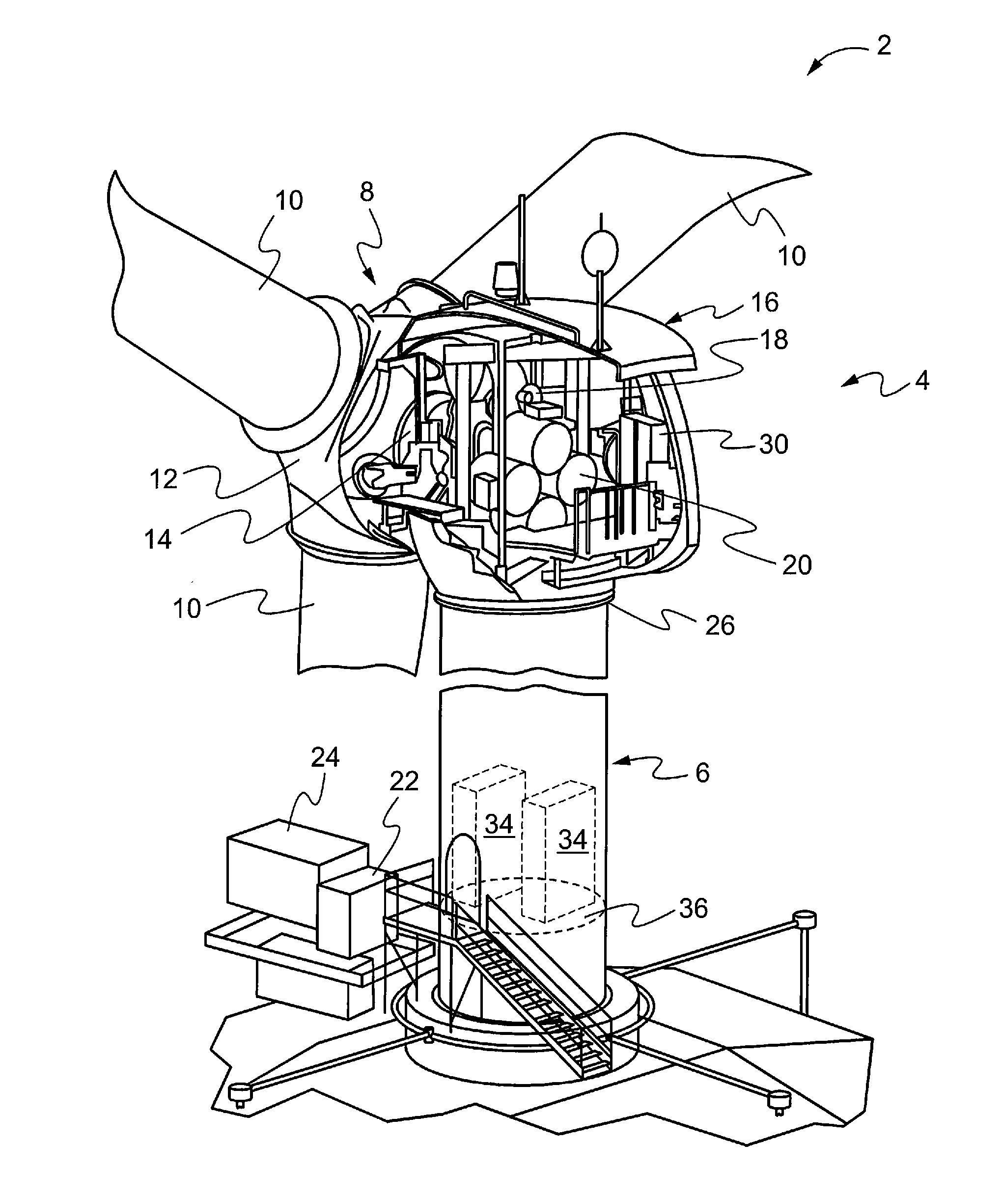
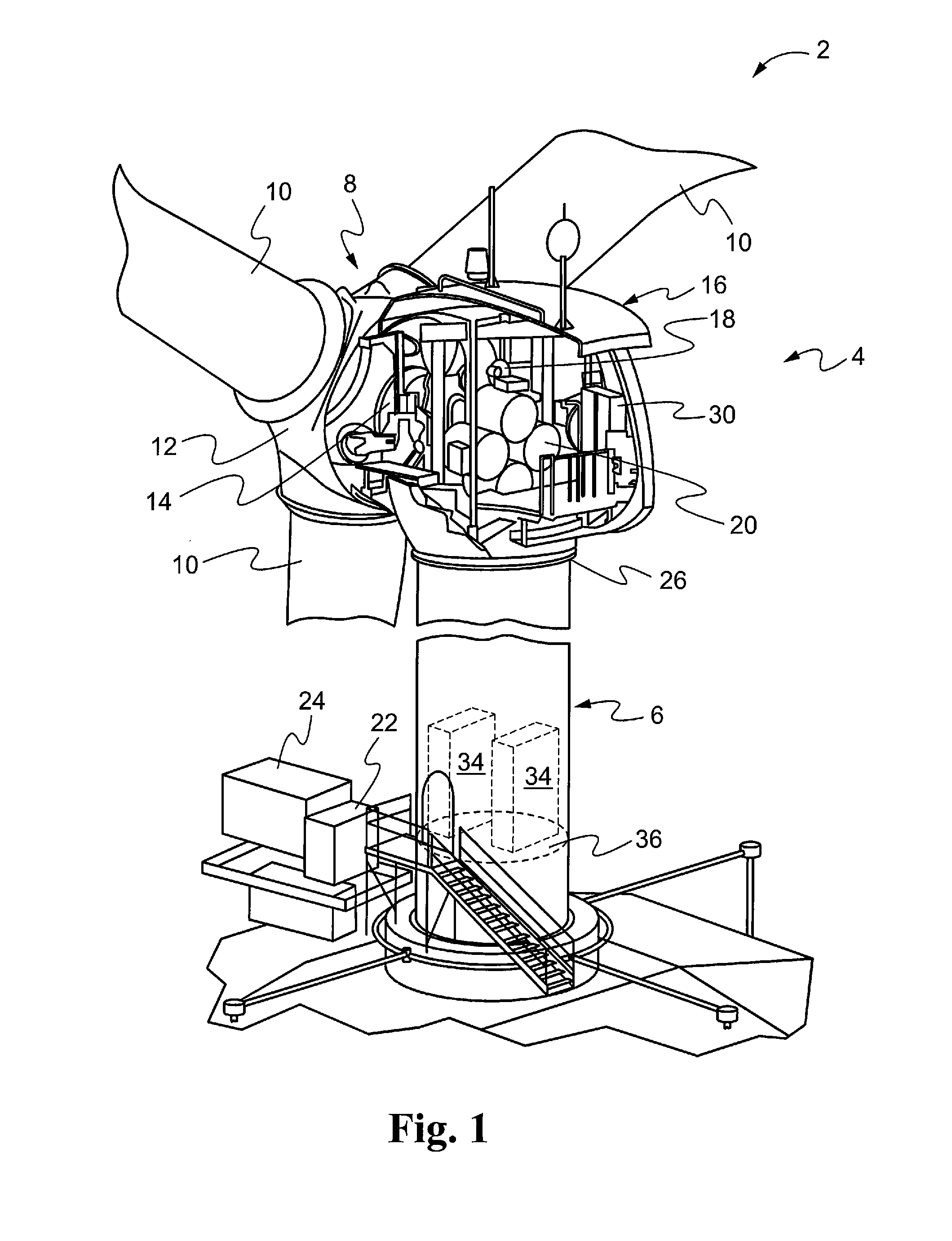
[0018]Referring now to FIG. 1, an exemplary wind turbine 2 is shown, in accordance with at least some embodiments of the present disclosure. While all the components of the wind turbine have not been shown and / or described, a typical wind turbine may include an up tower section 4 and a down tower section 6. The up tower section 4 may include a rotor 8, which in turn may include a plurality of blades 10 connected to a hub 12. The blades 10 may rotate with wind energy and the rotor 8 may transfer that energy to a main shaft 14 situated within a nacelle 16. The nacelle 16 may additionally include a drive train or gearbox 18, which may connect the main shaft 14 on one end to one or more generators 20 on the other end. The generators 20 generate electrical power, which may be transmitted from the up tower section 4 through the down tower section 6 to a power distribution panel (PDP) 22 and a pad mount transformer (PMT) 24 for transmission to a grid (not shown). The PDP 22 and the PMT 24 ...


PUM


Abstract

A system and method for automatically inspecting a lightning protection system on a wind turbine is disclosed. The system and method may include a wind turbine having a plurality of blades mounted to a hub, a lightning receptor on each of the plurality of blades, a lightning protection system extending from each of the lightning receptor to an earth grounding grid and a conductor that is part of a testing system extending from at least inside the hub, through the inside of at least one of the plurality of blades and connecting to the lightning receptor, the conductor completing a circuit extending from the lightning receptor to the earth grounding grid. A test current signal may be introduced into the testing system for a leg of the lightning protection system to be tested and an electrical continuity in the circuit using the test current signal may be determined.

Description

FIELD OF THE DISCLOSURE[0001]The present disclosure relates generally to wind turbines and, more particularly, relates to a system and method for automatically inspecting a lightning protection system on a wind turbine.BACKGROUND OF THE DISCLOSURE[0002]A utility-scale wind turbine typically includes a set of two or three large rotor blades mounted to a hub. The rotor blades and the hub together are referred to as the rotor. The rotor blades aerodynamically interact with the wind and create lift, which is then translated into a driving torque by the rotor. The rotor is attached to and drives a main shaft, which in turn is operatively connected via a drive train to a generator or a set of generators that produce electric power. The main shaft, the drive train and the generator(s) are all situated within a nacelle, which is situated on top of a tower.[0003]A utility-scale wind turbine also typically includes a lightning protection system. Wind turbines are frequently struck by lightnin...

Claims


Application Information

Patent Timeline
Patent Type & Authority Applications(United States)
IPC IPC(8): F03D11/00
CPCF03D17/00F03D80/30Y02E10/72
Inventor KISSINGER, JOSHUA PAUL
Owner CLIPPER WINDPOWER INC
Why Eureka
Try Eureka