Multi-spectral infrared imaging system for flare combustion efficiency monitoring

a multi-spectral infrared imaging and flare technology, applied in the field of multi-spectral infrared imaging systems, can solve the problems of no one having a good answer, the uncertainty of flare emissions is problematic for both regulators, and the determination of flare combustion efficiency and destruction and removal efficiency is extremely difficult, so as to achieve effective flare efficiency and reduce uncertainty , the effect of increasing efficiency

Active Publication Date: 2013-12-26
PROVIDENCE PHOTONICS
View PDF5 Cites 57 Cited by
  • Summary
  • Abstract
  • Description
  • Claims
  • Application Information

AI Technical Summary

Benefits of technology

[0016]The multi-spectral infrared imaging system described in this specification is aimed at providing real-time measurement of flare efficiency, which would enable operators to adjust flare operating conditions to achieve higher efficiency. Considering contributions of flare emissions in total volatile organic compound and hazardous air pollutant emission inventories, the potential environmental benefit could be tremendous. An effective flare efficiency measurement tool will enable better flare operations and mitigate extremely high flare emissions that may otherwise go undetected. The proposed multi-spectral infrared imaging system is expected to be effective for all types of flares under all kinds of operating conditions.

Problems solved by technology

Due to the intended function and nature of flare design and operations, determination of flare combustion efficiency (CE) and destruction and removal efficiency (DRE) is extremely challenging.
The fact is that no one has a good answer to this question and this level of uncertainty regarding flare emissions is problematic for both regulators and industry.
However, it is not practical to use the same approach to measure or monitor flare operations on a regular basis.
The performance of Telops's Hyper-Spectral Imager was less desirable.
This variability introduces unknown and uncontrollable factors into the pixel intensity-concentration equation, rendering calculations and results unreliable.
The IMACC FTIR also has a relatively long scan time (seconds) and suffers the same problem as the Telops Hyper-Cam.
If the IMACC FTIR is aimed at the fringe of the flare plume, or if the flare diameter is small, the effect of this temporal mismatch due to flare plume dynamics is expected to be much more salient and problematic.
This makes it impractical for routine monitoring as the system would need some sort of targeting system to ensure it is consistently aimed at the correct position in the flare plume while the plume may be constantly shifting in wind.
Both the Telops's Hyper-Cam and the IMACC FTIR are delicate research instruments and require expert-level personnel to operate.
They require significant effort to set up and maintain, and significant effort is required for post-processing / analyzing data in order to derive flare CE results.
They do not provide real-time or near real-time measurements, and are not suitable instruments to provide continuous real-time feedback to operational personnel.
The total ownership cost is very high (this is particularly true for Telops' Hyper-Cam).
The current problem is that there is no mechanism to measure flare efficiency and provide timely feedback to flare operators to adjust operating conditions for a higher efficiency.

Method used


Image

  • Multi-spectral infrared imaging system for flare combustion efficiency monitoring
  • Multi-spectral infrared imaging system for flare combustion efficiency monitoring
  • Multi-spectral infrared imaging system for flare combustion efficiency monitoring

Examples


Embodiment Construction

[0035]The present invention will now be described more completely with reference to the accompanying drawings, in which exemplary embodiments of the invention are shown.

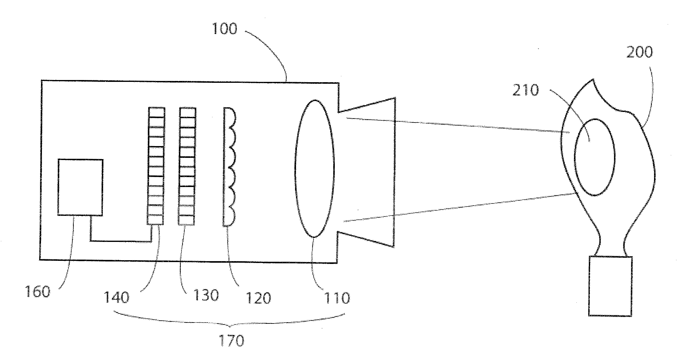
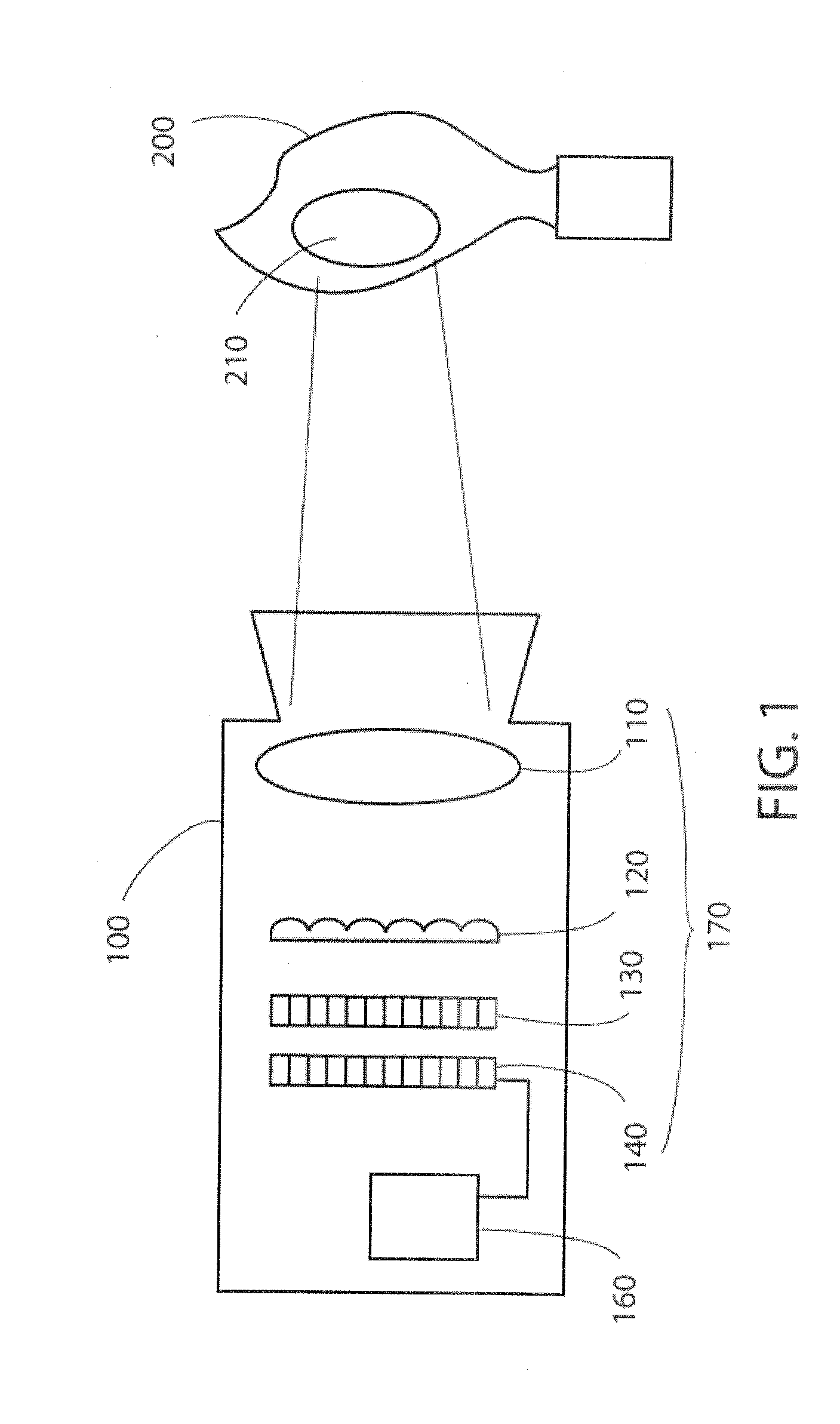
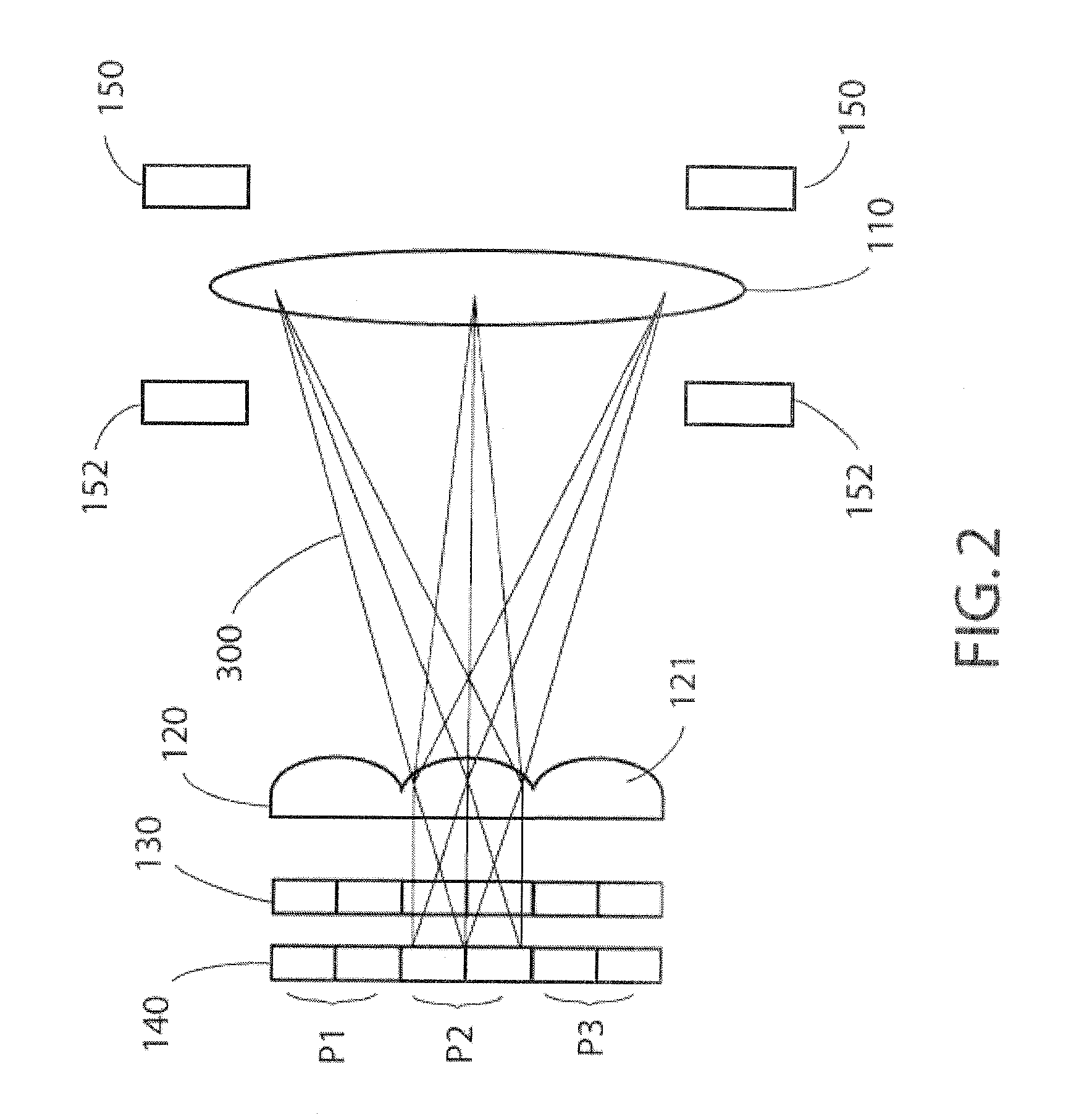
[0036]In the present invention, a multi-band infrared (IR) staring imager or imaging system for flare combustion efficiency (CE) measurement is proposed in order to overcome the problems described in the previous section and to be effective even under upset, emergency or routinely low flow conditions not covered by the TCEQ-UT study. The proposed IR imager utilizes a special arrangement of micro-lens array (MLA) optics which allow the imager to simultaneously image the flare in multiple spectral bands, each capable of imaging one gas. In one embodiment, the proposed multi-spectral IR imager has four spectral bands. The first band (Band 1), for example, can be set to take images of hydrocarbon (HC), the second band (Band 2) for carbon dioxide (CO2), the third band (Band 3) for carbon monoxide (CO), and the fourth band...


PUM


Abstract

The multi-spectral imaging system for real-time measurement of combustion efficiency of an industrial flare is provided. The system includes four spectral bands, one for a hydrocarbon group (fuel), one for carbon dioxide (CO2), product of complete combustion), one for carbon monoxide (CO, product of partially completed combustion), and one for background reference. More spectral bands can be added to measure combustion efficiency of specific compounds or enhance the background reference adjustment. The analysis apparatus includes a machine readable storage medium, which provides instructions that cause the analysis apparatus to perform operations to obtain the combustion efficiency of the flare. The operations includes acquiring at least three spatially and temporally synchronized intensities from an imaging unit capturing images of the flare, and producing the combustion efficiency of the flare from said at least three intensities, and absorption coefficients of materials contained in the flare.

Description

CLAIM OF PRIORITY[0001]This application claims priority under 35 U.S.C. §119 to Provisional Patent Application No. 61 / 662,781, entitled “MULTI-SPECTRAL INFRARED CAMERA FOR FLARE EFFICIENCY MEASUREMENT” filed on 21 Jun. 2012, and Provisional Patent Application No. 61 / 790,791, entitled “MULTI-SPECTRAL INFRARED IMAGING SYSTEM FOR FLARE EFFICIENCY MEASUREMENT” filed on 15 Mar. 2013, which applications are incorporated herein by reference.BACKGROUND OF THE INVENTION[0002]1. Field of the Invention[0003]The present invention relates to a multi-spectral infrared imaging system that provides real-time measurement of flare combustion efficiency, which would enable operators to adjust flare operating conditions to achieve higher efficiency. The multi-spectral infrared imaging system includes a machine readable storage medium, which provides instructions that cause the multi-spectral infrared imaging system to perform operations to obtain a combustion efficiency of a flare.[0004]2. Description ...

Claims


Application Information

Patent Timeline
Patent Type & Authority Applications(United States)
IPC IPC(8): H04N5/33
CPCH04N5/332G01J5/0014G01J2005/0077G01J5/0806H04N23/11
Inventor ZENG, YOUSHENGMORRIS, JONDOMBROWSKI, MARK
Owner PROVIDENCE PHOTONICS
Why Eureka
Try Eureka