Fluid delivery system and lift for use in conjunction therewith

Inactive Publication Date: 2013-12-26
AUTOMATION SOLUTIONS
View PDF4 Cites 4 Cited by
  • Summary
  • Abstract
  • Description
  • Claims
  • Application Information

AI Technical Summary

Benefits of technology

[0012]It is yet another object of the present invention to provide a system as described above wherein the device renders the bottles of fluid easily accessible for handling.
[0013]It is still another object of the present invention to provide a system as described above wherein the device allows for the level of fluid in each of the bottles of fluid to be readily visually ascertained.
[0014]It is yet still another object of the pr

Problems solved by technology

Although well-known in the art, the use of trays to support containers of fluid for laboratory analytic equipment has been found to suffer from a number of notable drawbacks.
As a first drawback, trays used to support containers of fluid for laboratory analytic equipment are typically maintained at a considerable height, especially when the analytic instrument on which it is mounted is in turn disposed on top of a laboratory bench.
As a consequence, it has been found that laboratory technicians are often unable to safely access containers that need to be replaced and/or refilled.
Rather, technicians in certain circumstances resort to climbing within the laboratory (e.g., using a stool, chair or the like), which inherently creates an unsafe environment for both the technician as well as the equipment.
As a second drawback, it has been found that the use of trays to support containers of fluid for laboratory analytic equipment can render the routine inspection of the containers to assess fluid levels rather difficult.
As a result of the height of the tr

Method used


Image

  • Fluid delivery system and lift for use in conjunction therewith
  • Fluid delivery system and lift for use in conjunction therewith
  • Fluid delivery system and lift for use in conjunction therewith

Examples


Example

Fluid Delivery System 11

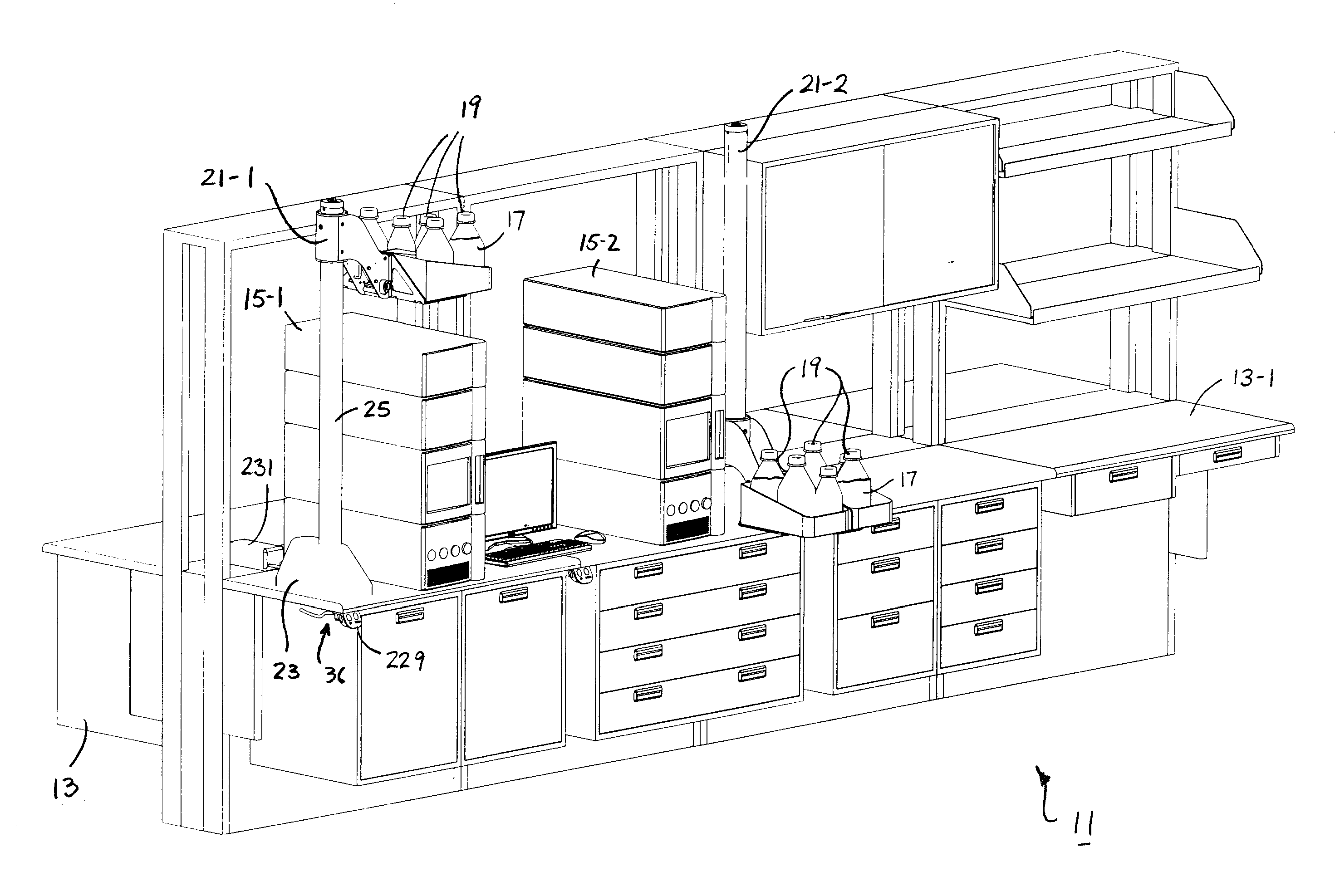
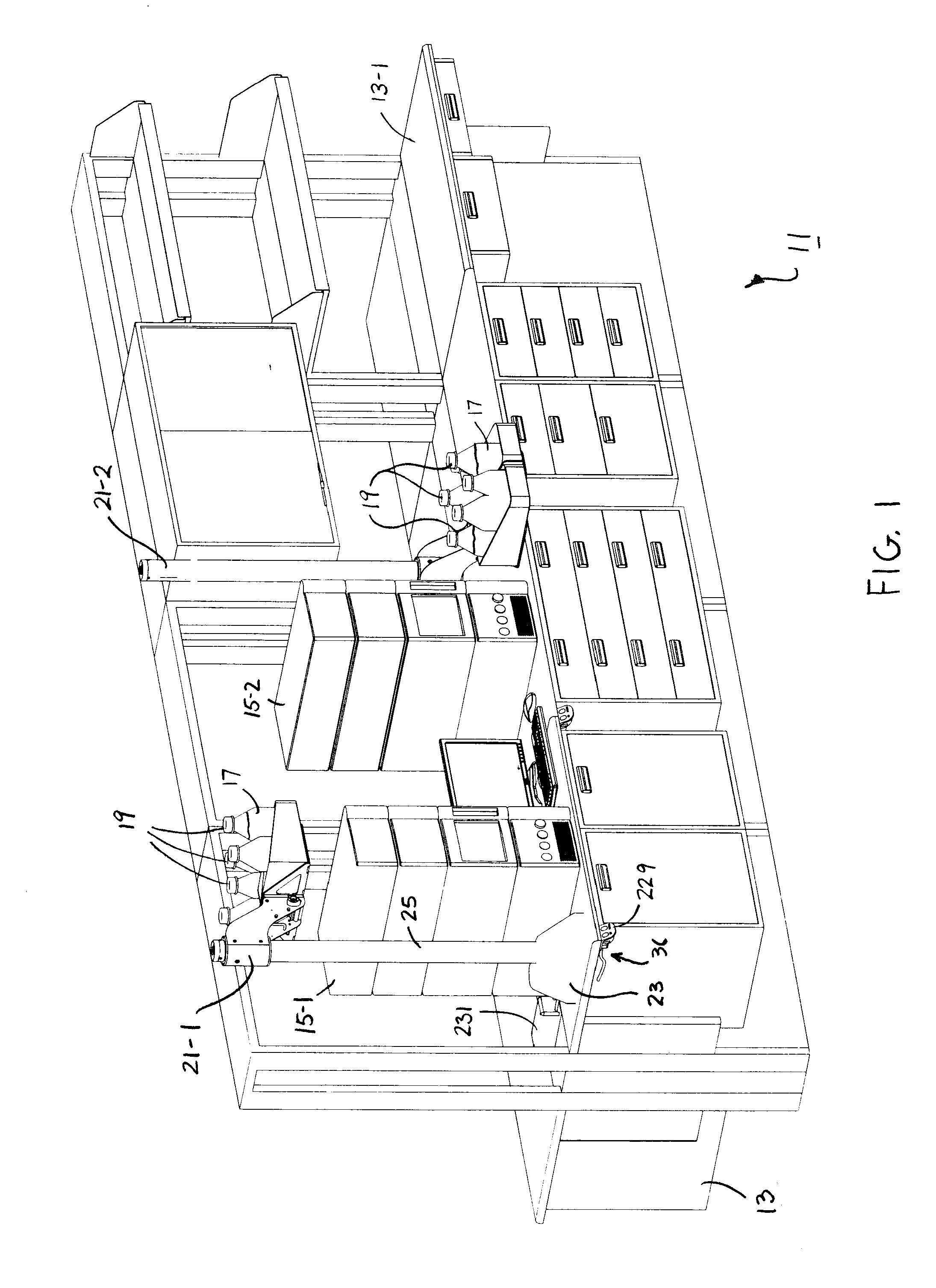
[0037]Referring now to FIG. 1, there is shown a fluid delivery system constructed according to the teachings of the present invention, the fluid delivery system being identified generally by reference numeral 11. As will be described in detail below, system 11 is designed primarily to improve safety in laboratory environments that rely upon gravity to feed fluids into test equipment.

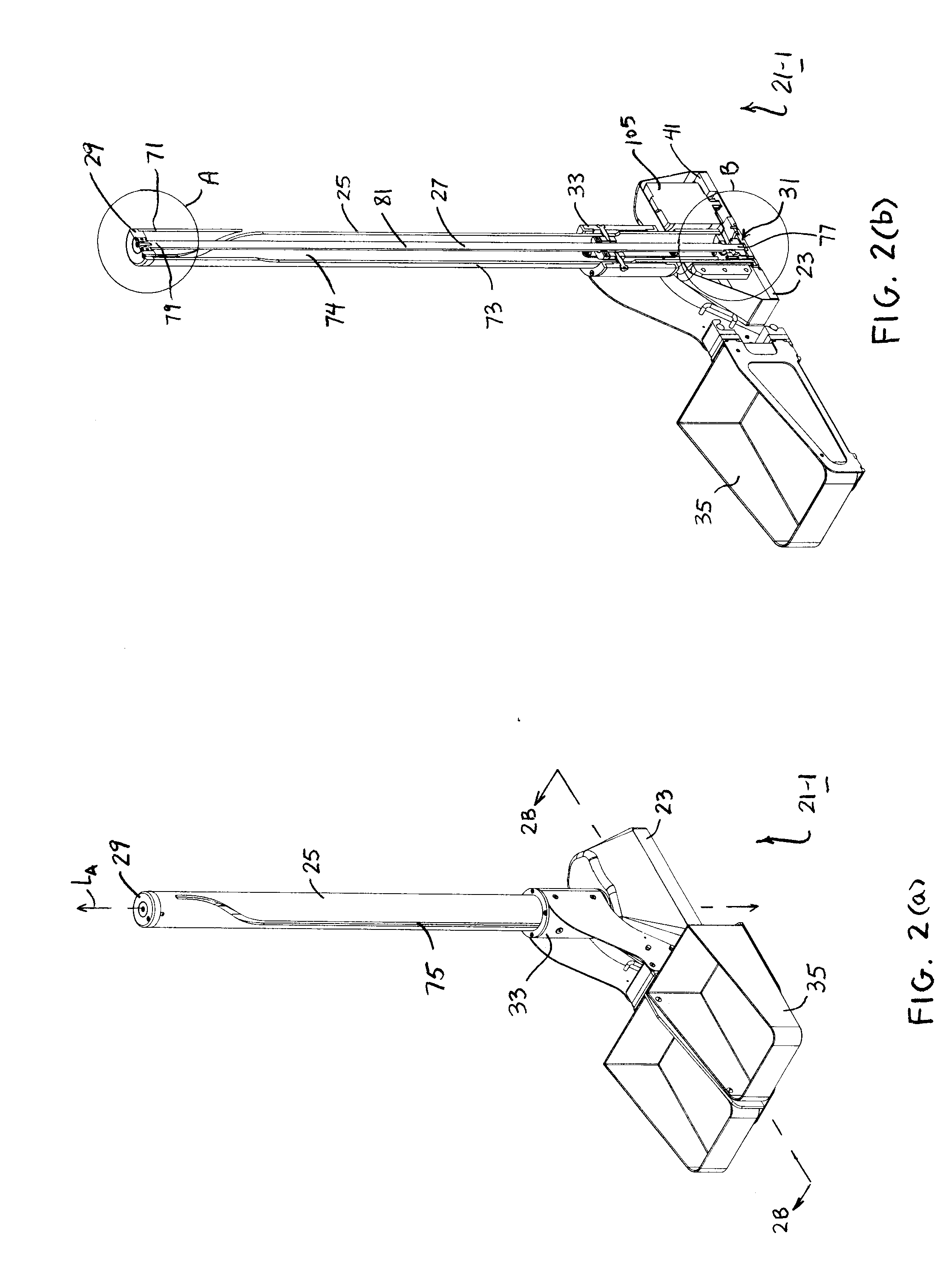
[0038]As shown herein, fluid delivery system 11 comprises a support structure 13, first and second laboratory analytic devices, or instruments, 15-1 and 15-2 disposed on support structure 13, each device 15 relying upon the delivery of a fluid 17 via gravity during normal operation, a plurality of containers 19, each container 19 being dimensioned to retain a supply of fluid 17, and first and second lifts 21-1 and 21-2 mounted on support structure 13, each lift 21 being adapted to support one or more containers 19 for a corresponding device 15. As will be described in detail below...


PUM


Abstract

A fluid delivery system includes a laboratory instrument that operates using fluid retained in one or more containers. The containers are supported on a motor-driven lift that is configured to transport the containers between a lowered position suitable for handling and an elevated position suitable for the delivery of fluid to the instrument by gravity. The lift includes a bench-mountable base, a tubular column extending upward from the base, an elongated lead screw extending longitudinally through the column, a drive mechanism for rotatably driving the lead screw, a carriage slidably mounted over the tubular column and mechanically coupled to the lead screw, a platform removably coupled to the carriage for supporting the containers, and a control system for regulating operation of the drive mechanism. During operation, a slot provided in the column restricts travel of the platform along a predefined path that is linear in part and helical in part.

Description

FIELD OF THE INVENTION[0001]The present invention relates generally to laboratory analytic equipment and more particularly to accessories for laboratory analytic equipment.BACKGROUND OF THE INVENTION[0002]In chemical laboratories, analytic instruments are commonly utilized to determine, inter alia, the mass, elemental composition and / or chemical structure of a sample. Examples of laboratory analytical instruments that are commonly utilized to determine properties associated with a sample include, but are not limited to, liquid chromatography units and mass spectrometers.[0003]Certain types of laboratory instruments utilize one or more fluids, such as common solvents, to modify chemical aspects of the sample as part of its analytical process. The fluids are traditionally retained within one or more bottles, or other similar containers, that are in turn fed into components of the analytic instrument by conduits, such as plastic tubing. In certain applications, the bottles of solution ...

Claims


Application Information

Patent Timeline
IPC IPC(8): B66F7/12B66F7/14
CPCB66F7/12B66F7/14B01L3/0293B01L9/00B01L2400/0457G01N35/1002
Inventor KENDALL, THOMAS MATTHEWTIERNEY, MATTHEW CHARLESCANTARA, JOSEPH SCOTT
Owner AUTOMATION SOLUTIONS
Why Eureka
Try Eureka