Laser reinforced direct bonding of optical components

a technology of optical components and lasers, applied in the field of assembly of optical components, can solve the problems of insufficient mechanical strength of the bonding surface, altering the optical properties affecting the performance of the resulting assembly, so as to achieve precise and local manner, and negligible alteration of the optical transmission properties.

Active Publication Date: 2013-12-26
UNIV LAVAL
View PDF3 Cites 48 Cited by
  • Summary
  • Abstract
  • Description
  • Claims
  • Application Information

AI Technical Summary

Benefits of technology

[0030]Advantageously, embodiments of the present invention can provide reinforced assemblies of optical components exhibiting hermetic and mechanically resistant bonds over a large area as well as negligible alteration of their optical transmission properties.
[0031]The methods and reinforced optical assemblies according to embodiments of the present invention rely on the use of ultrashort laser pulses to generate non-linear optical phenomena that allow depositing energy i

Problems solved by technology

Traditional techniques of assembling optical materials may induce mechanical stress, thereby deforming the bonded surfaces, or may result in a bonding having insufficient mechanical strength.
In addition, the bonded surfaces may present local or extended damages resulting from the bonding techniques themselves.
Moreover, due to the presence of visible bonding marks and residual surface deformations, these techniques may also alter the optical properties of the resulting assembly, such as its transparency or its reflectivity.
However, this method requires excessive pulse energy in comparison to what is really needed to induce non-linear absorption.
The strong non-linear absorption may also cause unwanted damage mechanisms.
This approach can however degrade the surface quali

Method used


Image

  • Laser reinforced direct bonding of optical components
  • Laser reinforced direct bonding of optical components
  • Laser reinforced direct bonding of optical components

Examples


Embodiment Construction

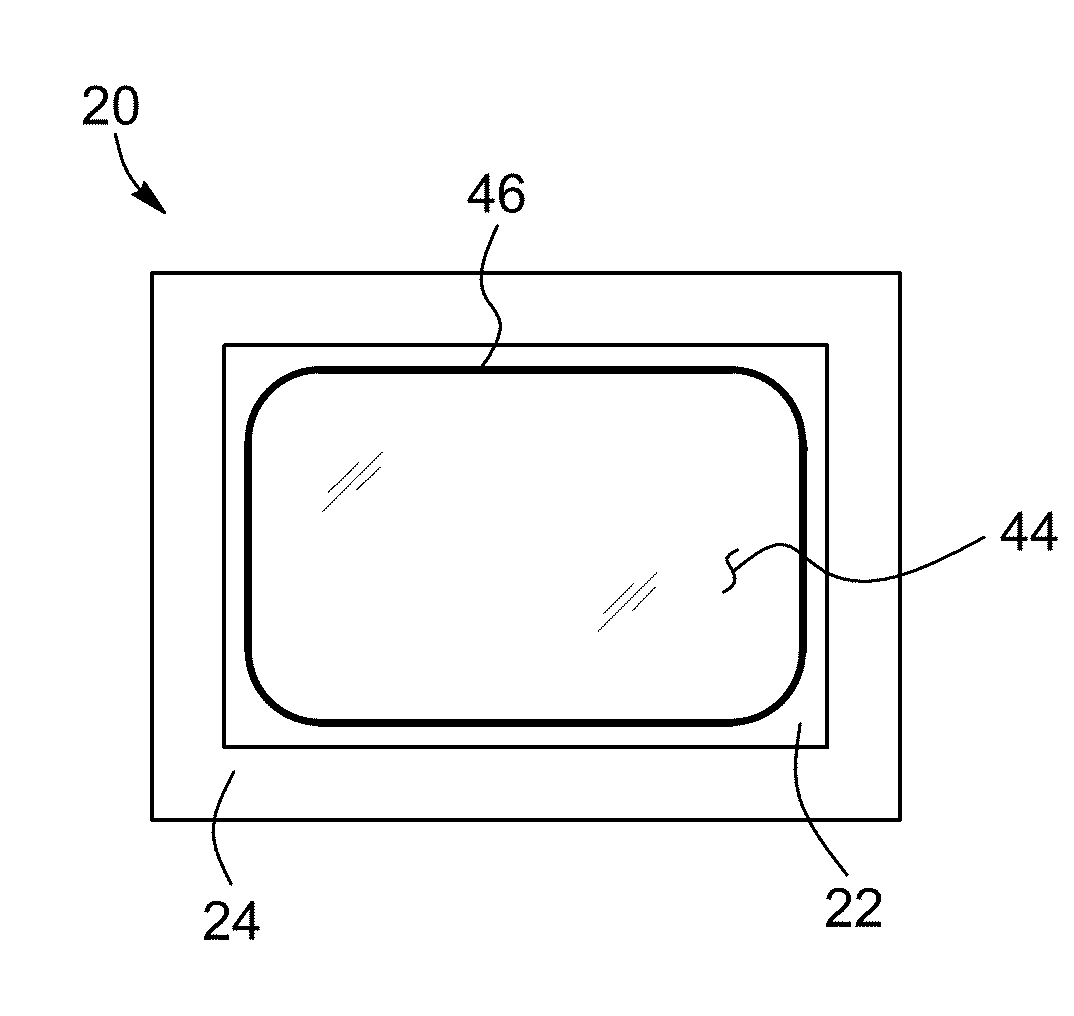
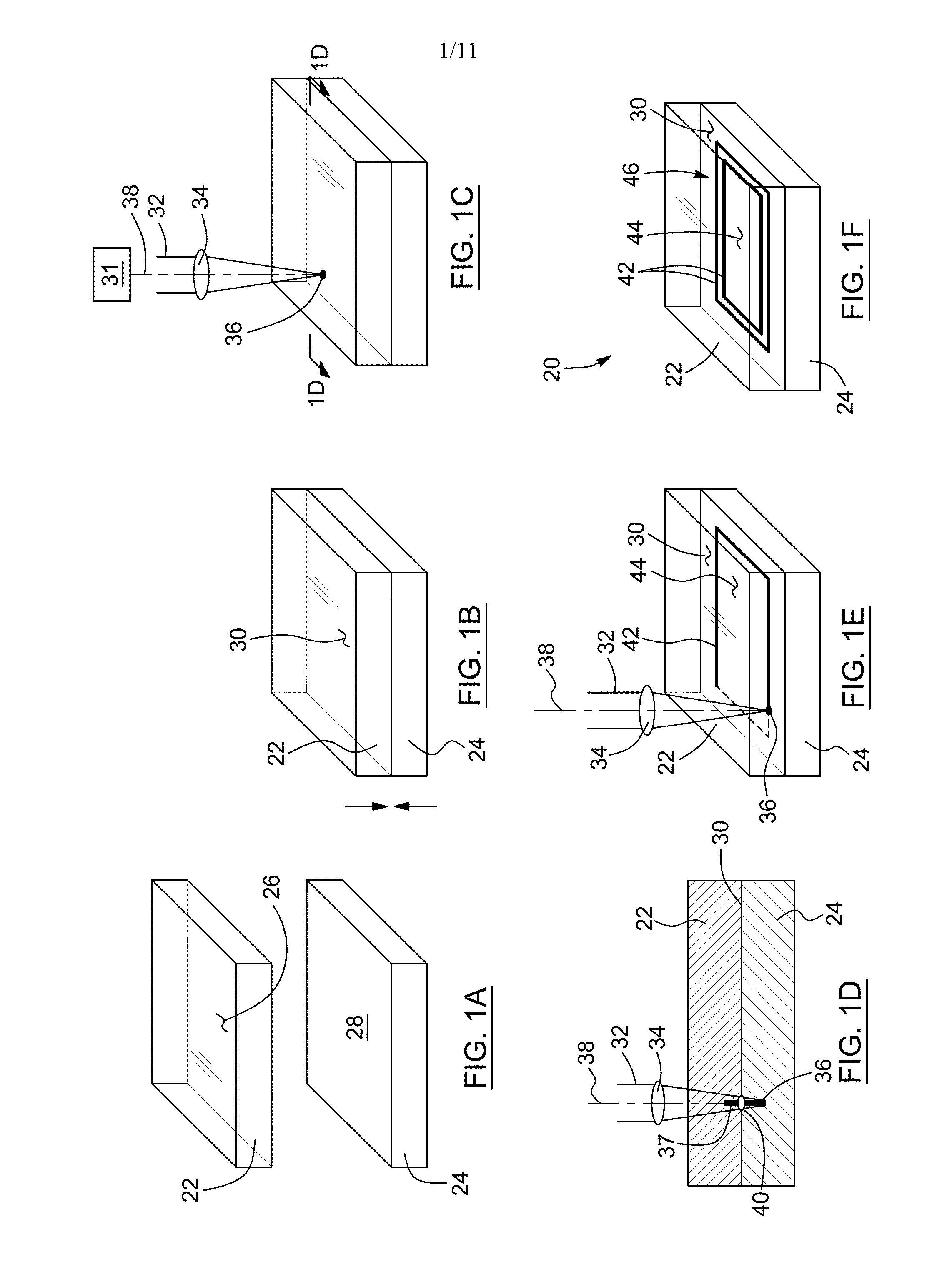
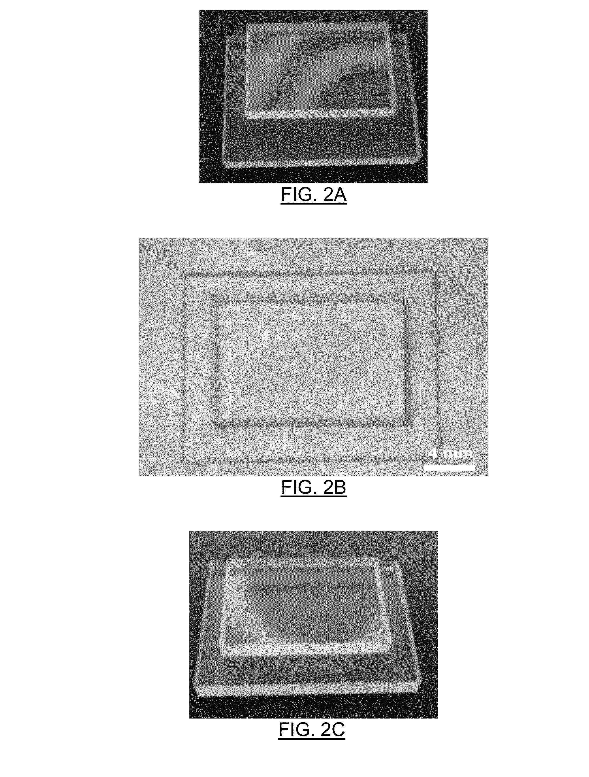
[0051]In accordance with one aspect of the invention, there is provided a method for joining together a first and a second optical component, each of the first and second optical components having a respective bonding surface.

[0052]It will be understood by those skilled in the art that the optical components that can be joined together by the method according to this aspect of the invention may be made up of any solid, non-plastically deformed material, provided that at least the first optical component is substantially transparent to the wavelength of the laser. As long as this requirement is fulfilled, each of the first and second optical components may thus be made up of single elements (e.g. Si, Ag, Al), compounds or organic compounds. Typical non-limiting examples of such compounds are glasses, crystals, metals, semiconductors, polymers and organic polymeric compounds such as polycarbonate, polytetrafluoroethylene (known under the trademark Teflon), and the like. It is an advan...


PUM

PropertyMeasurementUnit
Speedaaaaaaaaaa
Transmissionaaaaaaaaaa
Shapeaaaaaaaaaa

Abstract

A method for the laser reinforced direct bonding of two optical components having a respective bonding surface and a reinforced optical assembly made thereby are provided. The method includes a first step of assembling the two optical components by direct bonding of their respective bonding surface together, thereby defining a direct-bonded interface therebetween. The method further includes a second step of reinforcing the direct-bonded interface with a weld seam including at least one substantially continuous reinforcing weld line forming a dosed shape enclosing a sealed direct-bonded region. Each weld line is inscribed by focusing ultrashort laser pulses at the direct-bonding interface so as to generate non-linear optical phenomena inducing a localized junction between the two optical components. Advantageously, embodiments of the present invention provide reinforced optical assemblies exhibiting hermetic and mechanically resistant bonds over a large area as well as negligible alteration of their optical transmission properties.

Description

FIELD OF THE INVENTION[0001]The present invention relates to the field of assembling optical components, and more particularly concerns a method for the laser reinforced direct bonding of two optical components and a reinforced optical assembly made therebyBACKGROUND OF THE INVENTION[0002]The assembling of various materials such as glasses, crystals, metals, semiconductors, polymers and organic polymeric compounds for optical applications requires particular techniques for ensuring that the resulting assembly preserves a high surface quality as well as optimal optical transmission properties. In some cases, the use of a bonding material such as epoxy or other adhesive materials is to be avoided. Traditional techniques of assembling optical materials may induce mechanical stress, thereby deforming the bonded surfaces, or may result in a bonding having insufficient mechanical strength. In addition, the bonded surfaces may present local or extended damages resulting from the bonding te...

Claims


Application Information

Patent Timeline
IPC IPC(8): G02B27/00
CPCG02B27/00B23K26/0665B23K26/28B29D11/00B29C65/1635B29C65/1638B29C65/1658B29C66/1122B29C66/232B29C66/24244B29C66/41B29C66/45B29L2011/00B23K26/32B23K26/142B23K26/0624B23K26/60Y10T428/24802B23K26/53B23K26/57B23K2103/50
Inventor HELIE, DAVIDVALLEE, REALLACROIX, FABRICE
Owner UNIV LAVAL
Why Eureka
Try Eureka