Heat Exchangers with Floating Headers

a technology of heat exchangers and headers, which is applied in the field of heat exchangers, can solve the problems of premature failure of joints and/or heat exchanger components, stress in the joints between the various components and in the components, and potentially damaging stress on the tube to header joints, tubes, headers,

Active Publication Date: 2014-01-02
DANA CANADA CORP
View PDF6 Cites 17 Cited by
  • Summary
  • Abstract
  • Description
  • Claims
  • Application Information

AI Technical Summary

Benefits of technology

[0021]In another aspect, the first heat exchanger section comprises: (a) a single heat exchange tube having a first end, a second end and a hollow interior, the first and second ends being open; wherein the hollow interior of the heat exchange tube defines part of the first fluid flow passage; (b) a first header having a perforation in which the first end of the heat exchange tube is received in sealed engagement, wherein the first header has an outer peripheral edge which is sealingly secured to the inner shell wall; (c) a second header having a perforation in which the second end of the heat exchange tube is received in sealed engagement, wherein the second header has an outer peripheral edge which is sealingly secured to the inner shell wall, wherein a space enclosed by the inner shell and the first and second headers defines part of the second fluid flow passage; wherein the first header is attached to the first portion of the inner shell and the second header is attached to the second portion of the inner shell, such that the first axial gap between the first and second portions of the inner shell wall provides communication between the external connecting passage and the space enclosed by the inner shell and the first and second headers. For example, the heat exchange tube may comprise a corrugated tube wall.
[0022]In another aspect, the first heat exchanger section may comprise a concentric tube heat exchanger comprising: (a) an axially extending intermediate tube which is received within the inner shell wall and is spaced therefrom so that an outer annular space is provided between the inner shell wall and the intermediate tube, wherein the outer annular space comprises part of the second fluid flow passage; (b) an axially extending inner tube received within the intermediate tube and spaced therefrom so that an inner annular space is provided between the inner tube and the intermediate tube, wherein the inner annular space comprises part of the first fluid flow passage. For example, the intermediate tube may have expanded ends which are sealingly secured to the inner shell, and wherein the outer annular space is in communication with the second fluid outlet and in communication with the external connecting passage through said axial gap. Also, the intermediate tube may be provided with corrugations to permit axial expansion of the intermediate tube.

Problems solved by technology

These temperature differences can result in differential thermal expansion of the heat exchanger components, which can cause stresses in the joints between the various components and in the components themselves.
Over time, these stresses can cause premature failure of joints and / or the heat exchanger components.
This differential thermal expansion of the tubes and the shell causes potentially damaging stresses on the tube to header joints, as well as on the tubes, the headers, and the shell.

Method used


Image

  • Heat Exchangers with Floating Headers
  • Heat Exchangers with Floating Headers
  • Heat Exchangers with Floating Headers

Examples


first embodiment

[0040]A heat exchange device 10 according to the invention is now described below with reference to FIGS. 1 to 9.

[0041]Terms such as “upstream”, “downstream”, “inlet” and “outlet” are used in the following description to assist in describing the embodiments shown in the drawings. It will be appreciated, however, that these terms are used for convenience only, and that do not restrict the directions of fluid flow through the heat exchangers described herein. Rather, it is to be understood that the direction of flow of one or both fluids flowing through the heat exchangers may be reversed, where such flow reversal is advantageous.

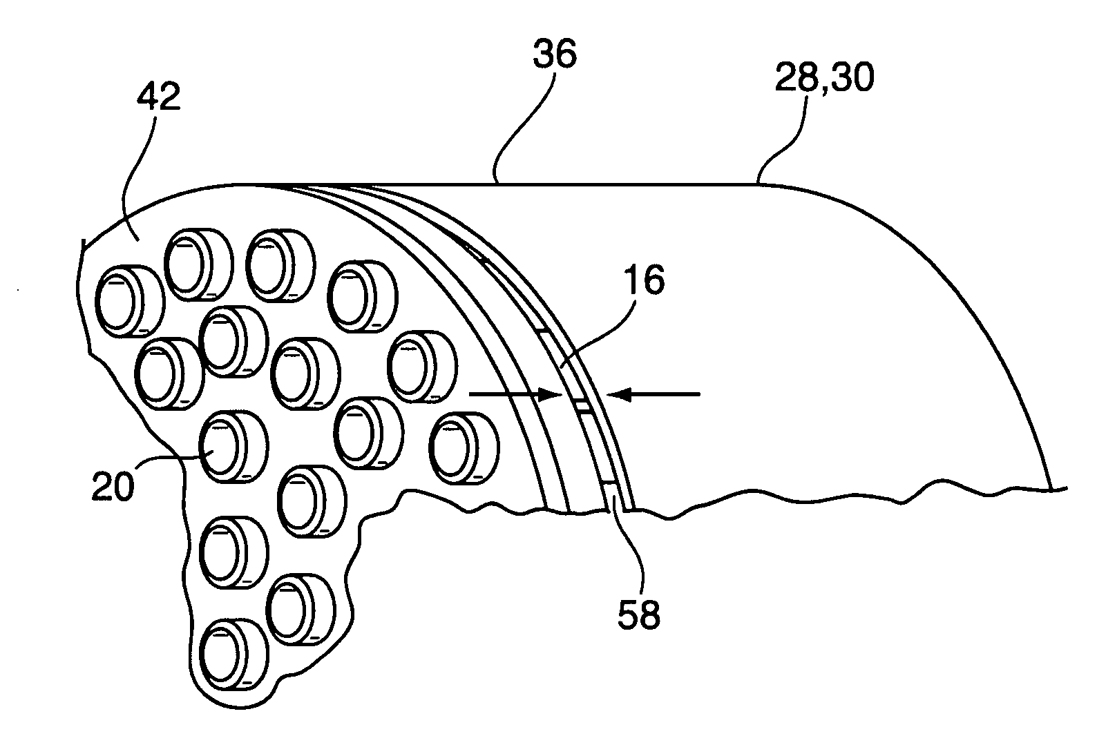
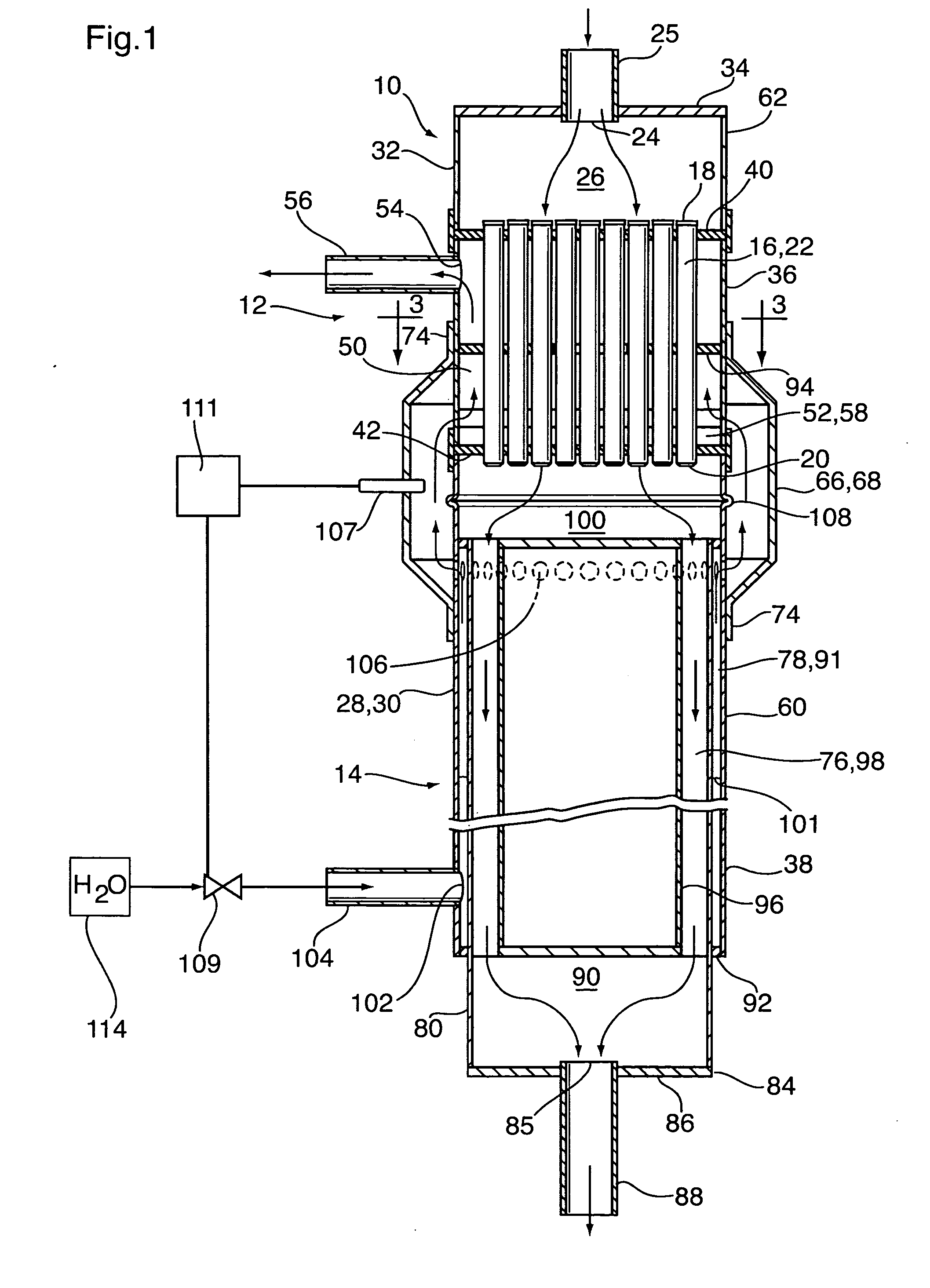
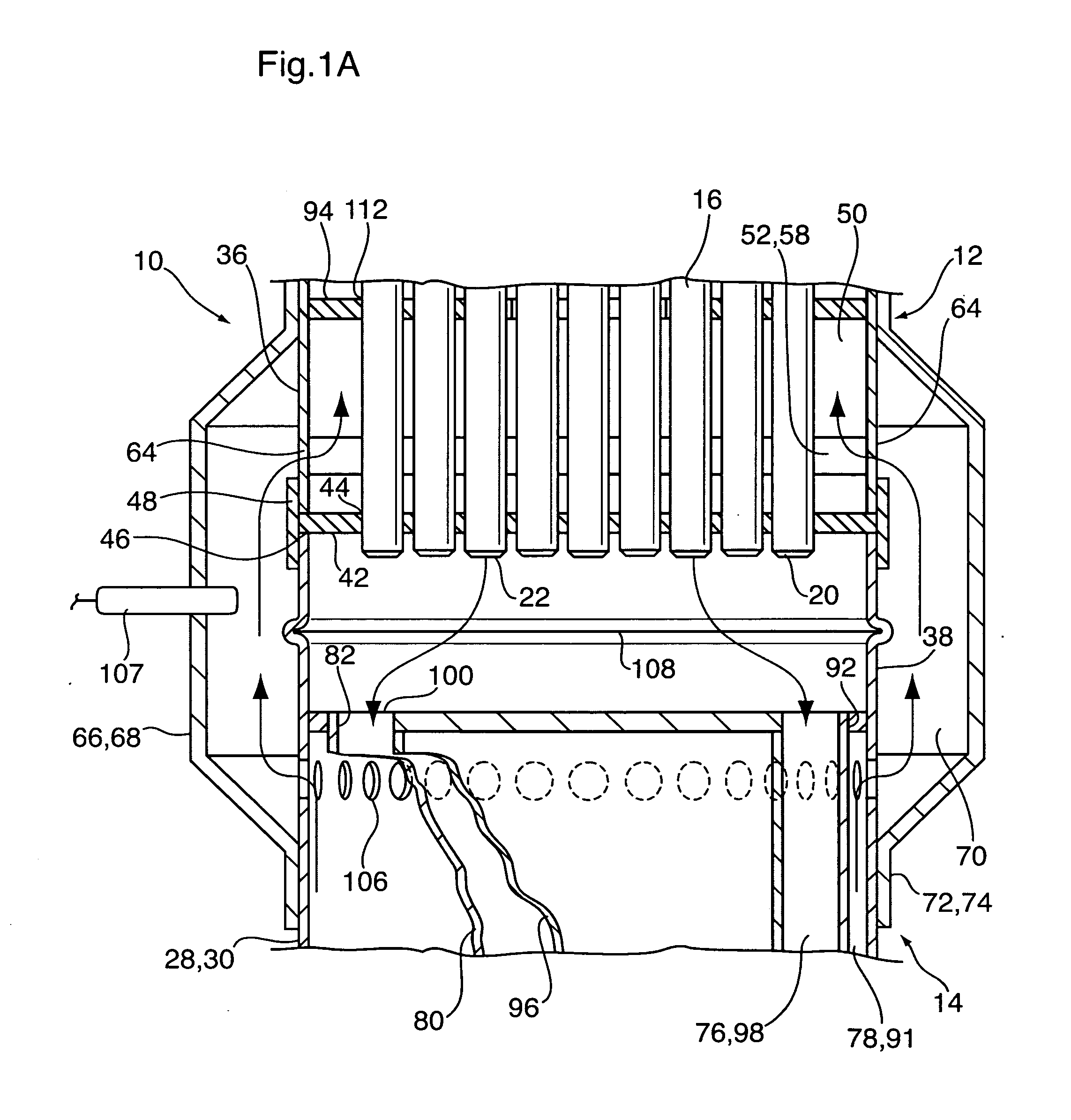
[0042]Heat exchange device 10 is a steam generator or combined steam generator and catalytic converter in which heat from a hot waste gas (tail gas) is used to convert liquid water to superheated steam. Steam generator 10 generally comprises two heat exchanger sections, a first heat exchanger section 12 comprising a shell and tube heat exchanger and a second ...

second embodiment

[0084]A heat exchanger 200 according to the invention is now described with reference to FIG. 10.

[0085]The heat exchanger 200 according to the second embodiment comprises a water gas shift reactor in which a hot synthesis gas (hereinafter “syn gas”) is simultaneously cooled and reduced in carbon monoxide content. The water gas shift reactor 200 may be incorporated into a fuel cell system, and may be located downstream of a syn gas generator, such as a fuel reformer, in which the syn gas is produced from a hydrocarbon fuel. The syn gas typically comprises hydrogen, water, carbon monoxide, carbon dioxide and methane. Prior to being used in a fuel cell, the syn gas must be cooled and the carbon monoxide content must be reduced. The syn gas therefore undergoes a slightly exothermic catalytic reaction in the water gas shift reactor 200, converting carbon monoxide and water to carbon dioxide and hydrogen. One or more water gas shift reactors 200 may be required to reduce the carbon monoxi...


PUM


Abstract

A heat exchanger is comprised of two heat exchanger sections, at least one of which is provided with a floating header to accommodate differential thermal expansion. The two heat exchanger sections are enclosed by an inner shell wall, and an external connecting passage is provided outside the inner shell wall, through which one of the fluids flows between the two heat exchanger sections. The external connecting passage is enclosed by an outer shell. The inner wall is provided with openings which communicate with the external connecting passage. The openings may be in the form of a substantially continuous gap or discrete openings. Specific examples of heat exchangers with this construction include a steam generator, a steam generator and combined catalytic converter, and a water gas shift reactor.

Description

FIELD OF THE INVENTION[0001]The invention relates to heat exchangers having at least one heat exchanger section which may have a shell and tube construction, and in particular to such heat exchangers in which axial thermal expansion of the tubes is accommodated by the provision of a floating header.BACKGROUND OF THE INVENTION[0002]Heat exchangers are commonly used for transferring heat from a very hot gas to a relatively cool gas and / or liquid. Significant temperature differences can exist between those parts of the heat exchanger which are in contact with the hot gas and those parts which are in contact with the cooler gas and / or liquid. These temperature differences can result in differential thermal expansion of the heat exchanger components, which can cause stresses in the joints between the various components and in the components themselves. Over time, these stresses can cause premature failure of joints and / or the heat exchanger components.[0003]In a typical shell and tube he...

Claims


Application Information

Patent Timeline
Patent Type & Authority Applications(United States)
IPC IPC(8): F28D7/10F28F27/00
CPCF28D7/16F28F9/00F28F9/26F22B9/04F28D7/0066F28D7/10F28D21/001F28D2021/0024F28D2021/0064F28F9/0239F28F9/0241F28F27/00F28F2009/226F28F2265/26
Inventor VANDERWEES, DOUGHASAN, MANAFHUANG, JIANANCHEADLE, BRIAN E.
Owner DANA CANADA CORP
Why Eureka
Try Eureka