
Production of dry alcohol

a technology of dry alcohol and distillation process, which is applied in the direction of oxygen compound purification/separation, light and heating apparatus, chemical production, etc., can solve the problems of large amount of energy, large amount of distillation process, and considerable additional energy, and achieve the effect of increasing the energy efficiency of the process

Active Publication Date: 2007-10-11
RCM TECH USA INC
View PDF9 Cites 30 Cited by
  • Summary
  • Abstract
  • Description
  • Claims
  • Application Information

AI Technical Summary

Benefits of technology

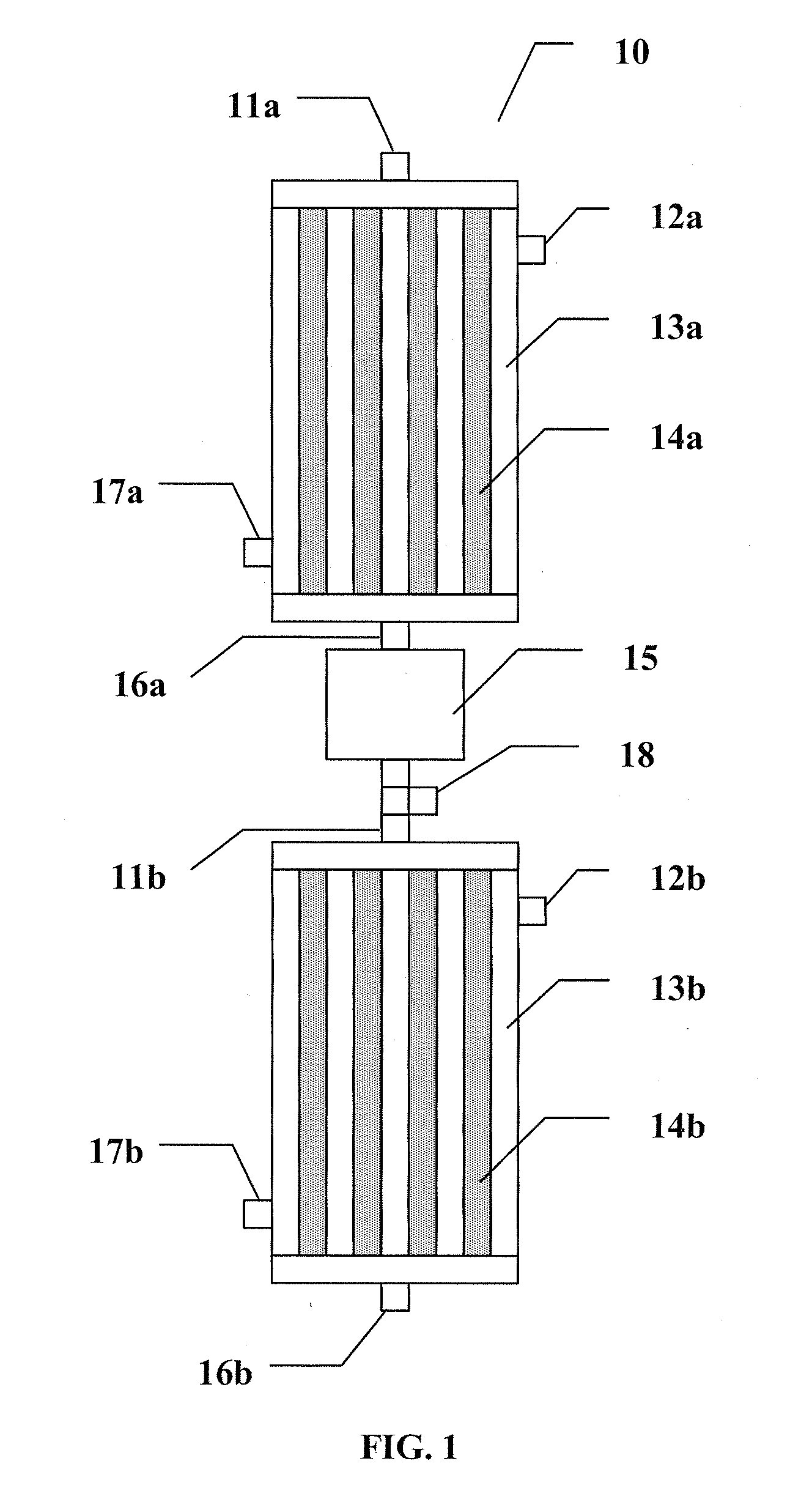
[0041]The water-gas shift reaction used to dry the alcohol also liberates heat. Preferably the heat generated is used to increase the energy efficiency of the process. In one embodiment, the heat is used to generate high-pressure steam. The high-pressure steam may be used, for example, to convert feedstock to gaseous feedstock or in other stages of a production plant.

Problems solved by technology

Distillation processes have the further drawback that they require a large amount of energy.
% ethanol content level and typically require a considerable additional amount of energy.
The high energy cost of ethanol separation by distillation is an economic impediment for using ethanol produced by alcoholic fermentation as an engine fuel.
While the benzene-water-ethanol ternary is probably the most widely used method of dehydrating ethanol, it require the expenditure of a great deal of heat energy.
All of these reagents have disadvantages in that they must be extensively treated to remove the water before they can be reused.
Salt distillation is accompanied by several problems, the most important of which is corrosion.
Feeding and dissolving the salt also represents a potential problem; the solubility of salt is low in the reflux because it contains the more volatile component (ethanol), while the salt will be most soluble in the less volatile component accumulated at bottom.
Unfortunately, water can be completely removed only by using large excess of isobutylene, and some of the ethanol is converted to its t-butyl ether.
Copper-zinc shift catalysts are extremely sulfur intolerant, being irreversibly poisoned even with small quantities of sulfur compounds.
The low temperature catalysts can be also irreversibly damaged by temperatures above 360° C.
The use of the water-gas shift reaction is reported as a means of removing carbon monoxide from the hydrogen formed, since excess carbon monoxide can interfere with the functioning of fuel cells.
However, the process described in U.S. Pat. No. 6,387,554 does not produce dry ethanol.

Method used


Image

  • Production of dry alcohol
  • Production of dry alcohol
  • Production of dry alcohol

Examples


example 1

Inventive-Simulation

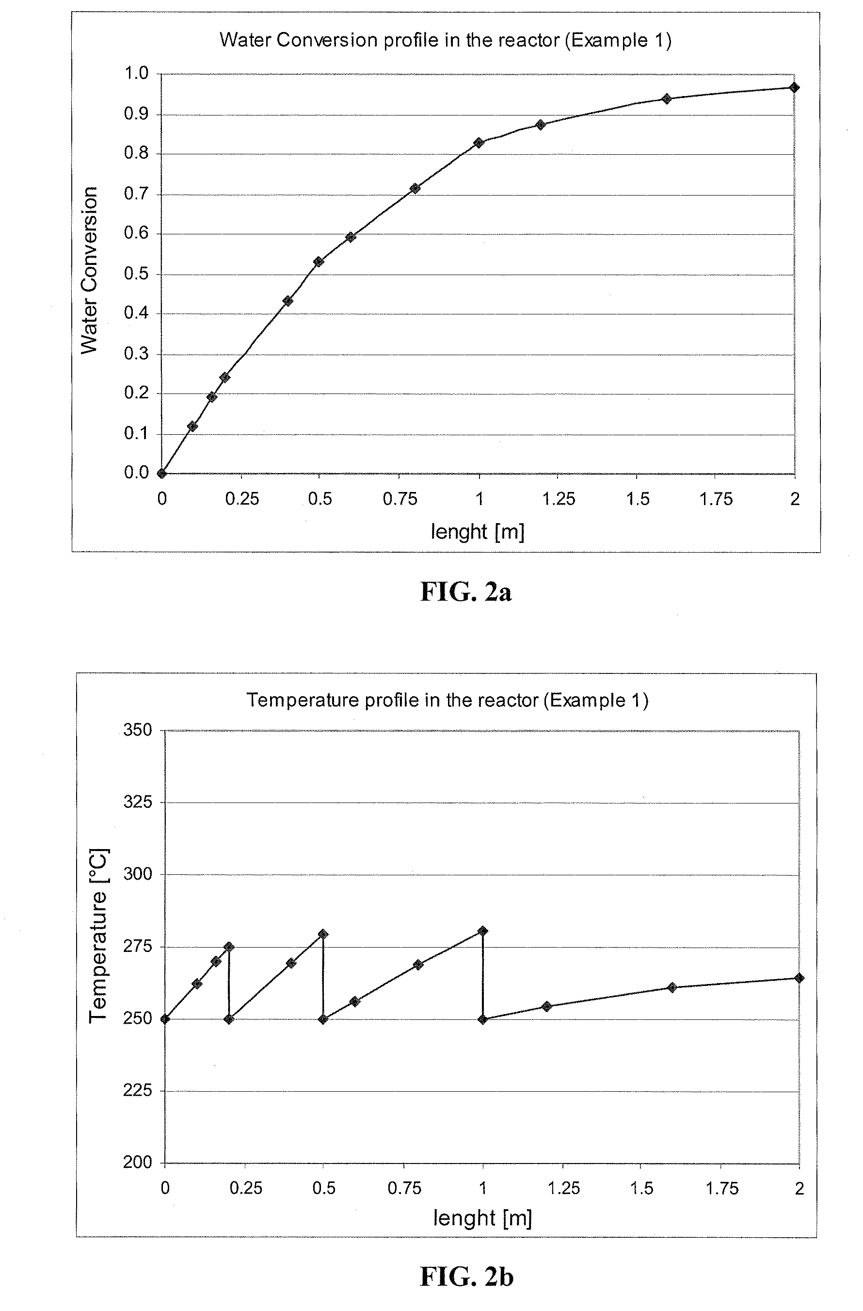
[0108]Water-gas shift in the adiabatic multistage reactor with cooling between stages—10 wt % of water in the feed.

[0109]The reactor is 2 meters long and consists of 4000 tubes, each 1″ in diameter. The reactor operates at 3.4 atm of pressure. The reactor has three quenching points at 10, 25 and 50% of reactor length, and thus, the reactor is divided into four stages. The first stage is 0.2 meters long, the second stage is 0.3 meters long, the third stage is 0.5 meters long, and the final stage is 1 meter long.

[0110]A feed of 20, 510 kg / hr (45,000 lb / hr) of a mixture of ethanol and water containing 10 wt % of water is injected at a temperature of 250° C. into the four-stage adiabatic reactor with cooling between stages. The amounts of catalyst at the four stages are, in order, 405, 608, 1013 and 2026 liters. The molar excess of CO relative to H2O is 2 and the velocity in the bed is 1.3 m / sec. The exit temperature after each stage is lowered to 250° C. by use of a...

example 2

Inventive-Simulation

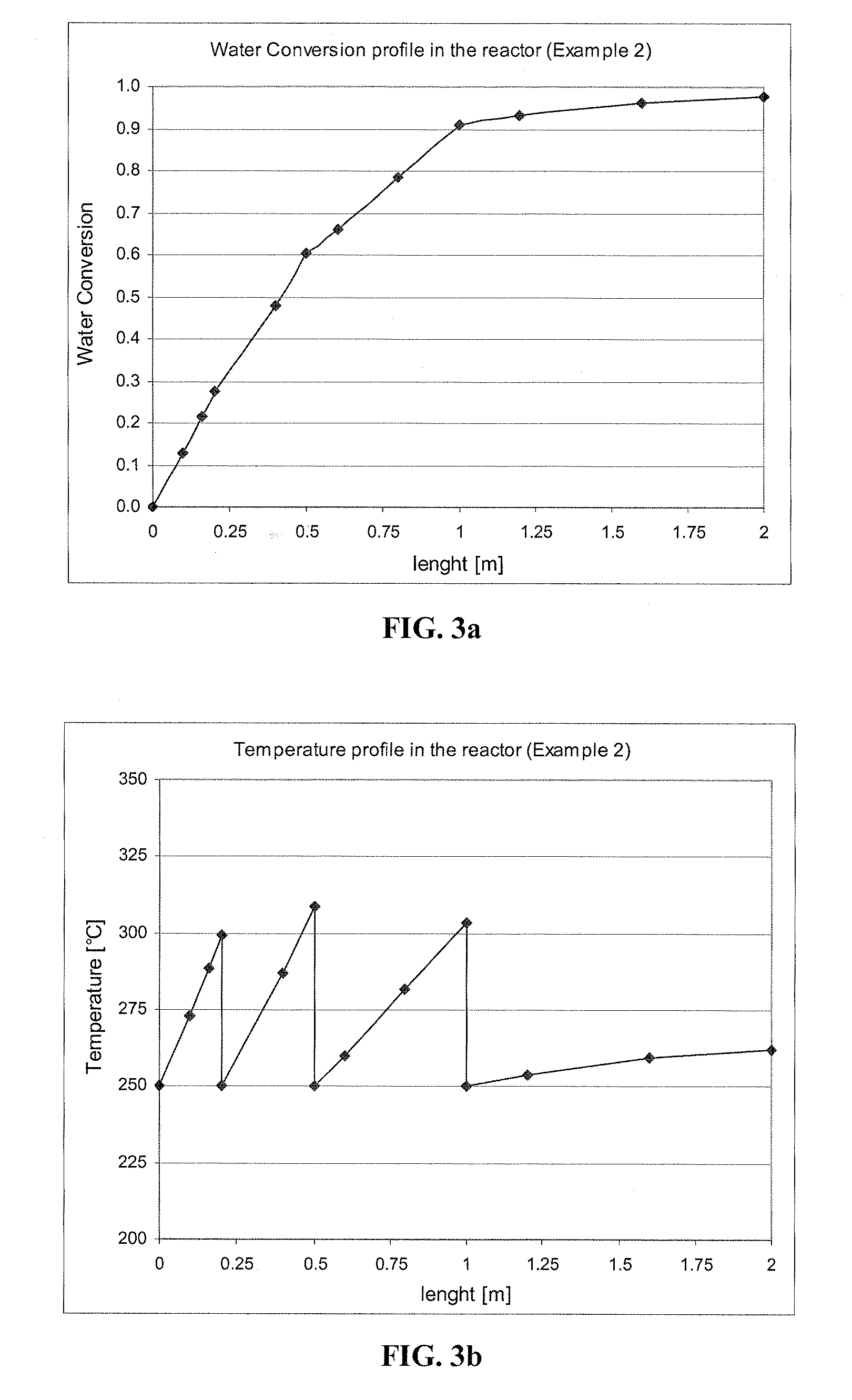
[0113]Water-gas shift in the adiabatic multistage reactor with cooling between stages—20 wt % of water in the feed.

[0114]The conditions are the same as in Example 1, except that the inlet gas contains 20 wt % of water. The velocity in the bed is 1.8 m / sec. The conversions at the four stages are 0.275, 0.604, 0.909 and 0.978, and the exit temperatures are 299.2, 308.5, 303.8 and 262.3° C., respectively. Water conversion and Temperature profiles are shown on FIG. 3a and FIG. 3b, respectively.

[0115]The composition of the final exit gas is 0.48% water, 22.39% CO, 21.43% CO2, 21.43% H2 and 34.27% ethanol (molar fractions). After condensation of ethanol and water and absorption of CO2 in ethanolamine, the gas contains 51.09% CO and 48.91% H2. In the process, 97.8% of the water is removed, and the purity of the ethanol after condensation is 99.5 wt %.

example 3

Inventive-Simulation

[0116]Water-gas shift reaction in a cooled first stage tubular reactor (thus non-adiabatic) is followed by an adiabatic 2 stage reactor with cooling between stages.

[0117]A reactor inlet stream is produced by mixing pure CO from a carbon combustor with overhead vapor from a beer column containing 66 wt % water and 20% of recycle stream. Recycle stream refers to a gas stream that was used in a previous process cycle and in which any ethanol and water were removed by condensation, and CO2 was removed by an absorptive means. The recycle stream includes CO as well as H2 that was produced in a previous cycle.

[0118]The mixture, which contains 33.33% water, 16.66% ethanol, 33.33% CO, 8.33% CO2 and 8.33% H2 is injected at a rate of 4,574 kmol / hr into a first stage tubular non-isothermal non-adiabatic reactor with 6,000 tubular reaction spaces (tubes), 2.54 cm (1 inch) internal diameter, each 6 m long, operating at 227° C. (inlet) and 5 atmospheres pressure. The stream en...


PUM

PropertyMeasurementUnit
Temperatureaaaaaaaaaa

Abstract

A process for producing dry alcohol includes at least one stage wherein a gaseous feedstock, which includes alcohol and water, is contacted with carbon monoxide in the presence of a water-gas shift catalyst, at a temperature sufficiently high so that carbon monoxide and water are consumed and carbon dioxide and hydrogen are produced, thereby removing a portion of the water. The process may include multiple stages; the dry alcohol produced contains 99.5 wt. % or greater of alcohol and 0.5 wt. % or less of water. A preferred alcohol is ethanol; dry ethanol can be combined with gasoline to afford a gasohol.The water-gas shift reaction is exothermic. The heat generated may be used to increase the energy efficiency of the process. In one embodiment, the heat is used to generate high-pressure steam. The high-pressure steam may be used, for example, to convert feedstock to gaseous feedstock or in the operation of a production plant.

Description

CROSS REFERENCE TO RELATED APPLICATIONS[0001]This application claims the benefit of Provisional Patent Application No. 60 / 744,430, which was filed Apr. 7, 2006.FIELD OF THE INVENTION[0002]The present invention is directed to the purification of alcohol and, more particularly, to a process and an apparatus for the removal of water from mixtures of alcohol and water and the production of dry alcohol with simultaneous generation of energy. In certain cases, dry alcohol can be used as a fuel additive, and this energy efficient process further reduces reliance on fossil fuels.BACKGROUND OF THE INVENTION[0003]Decreasing world reserves and diminishing availability of crude oil have created considerable incentive for the development and use of alternative fuels. In recent years, the ever increasing value of fossil hydrocarbon liquids and gases has directed research and development to the possibilities of employing bio-mass materials for fuel purposes. In particular, attention has been focus...

Claims


Application Information

Patent Timeline
IPC IPC(8): C07C29/74
CPCC01B3/16C07C29/1518C07C29/88F22G1/14C07C31/04C07C31/08Y02P20/52Y02P20/10Y02E50/10
Inventor BROWN, CHRISTOPHER J.SIMO, MARIANHLAVACEK, VLADIMIR
Owner RCM TECH USA INC
Learn More