Turbine for an exhaust gas turbocharger

a turbocharger and turbine technology, applied in the direction of machines/engines, stators, liquid fuel engines, etc., can solve the problems of significant efficiency drop and impair the overall efficiency of the turbine, and achieve the effect of high efficiency, increased mass supply of the first spiral channel to the turbine wheel, and efficient operation

Active Publication Date: 2014-01-02
IHI CHARGING SYST INT
View PDF8 Cites 11 Cited by
  • Summary
  • Abstract
  • Description
  • Claims
  • Application Information

AI Technical Summary

Benefits of technology

[0025]In another advantageous embodiment of the invention, a mass supply of exhaust gas to the turbine wheel is variably provided via the first and/or the second, in particular via the first, spiral channel, in the peripheral direction of the turbine wheel. In other words, a mass supply of exhaust gas to the turbine wheel, viewed over the periphery in the peripheral direction of the turbine wheel, is not constant. Thus, a mass supply which is nonuniform viewed over the periphery in the peripheral direction of the turbine wheel is counteracted by the segmentation, in which the mass supply to the turbine wheel is reduced via the first spiral channel in the first angular range, for example. The turbine according to the invention thus has particularly efficient operation and high efficiency. This nonuniform mass supply is achieved, for example, in that an NR ratio associated with the second spiral channel is variable in the peripheral direction of the turbine wheel, where A denotes a spiral or center-of-mass surface area of the second spiral channel via which the turbine wheel may be acted on by exhaust gas, and R denotes a center-of-mass [radius] of the second spiral channel.
[0026]Additionally or alternatively, it may be provided that an NR ratio associated with the first spiral channel is variable in the peripheral direction, where A denotes a spiral or center-of-mass surface area of the first spiral channel via which the turbine wheel is acted on by exhaust gas, and R denotes a center-of-mass radius of the first spiral channel. When the A/R ratio of the second spiral channel is reduced in particular close to the minimum of 0, the mass supply of the first spiral channel to the turbine wheel may be increased. This brin

Problems solved by technology

However, it has been shown that this results in a significant drop in efficiency in particu

Method used


Image

  • Turbine for an exhaust gas turbocharger
  • Turbine for an exhaust gas turbocharger
  • Turbine for an exhaust gas turbocharger

Examples


Embodiment Construction

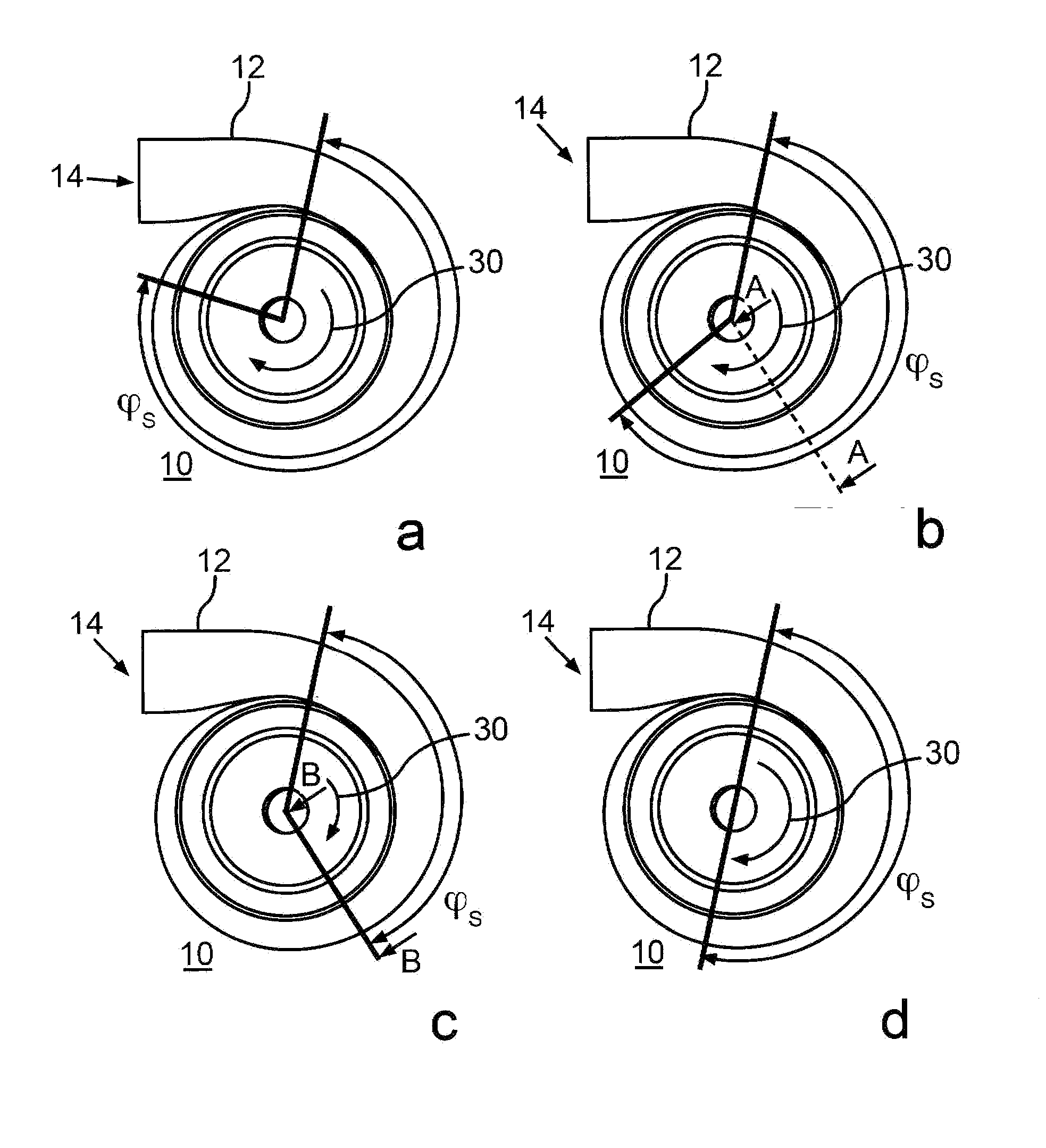
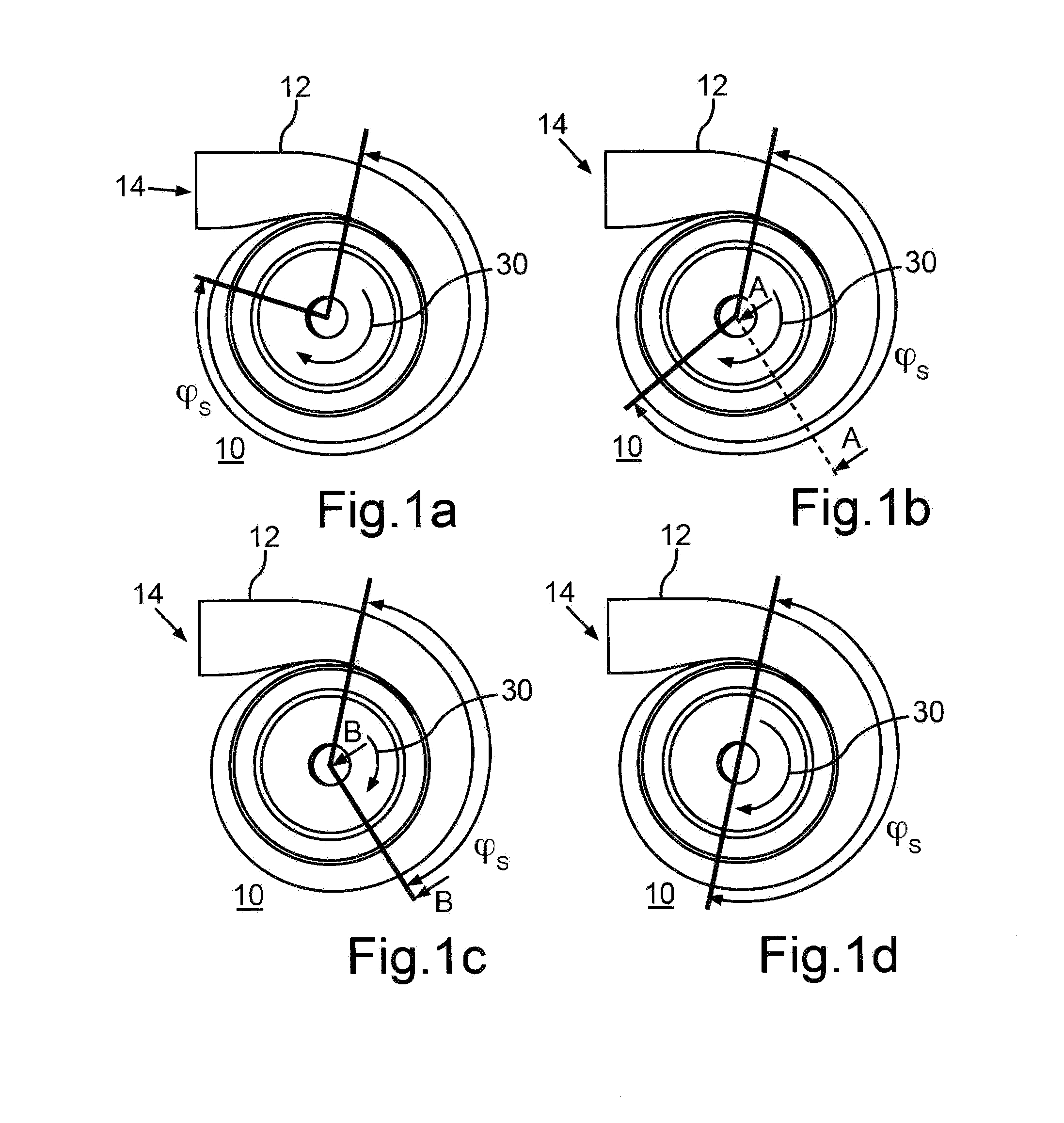
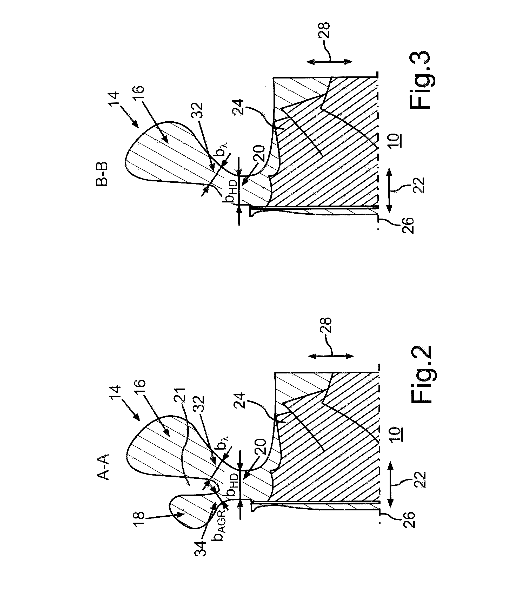
[0038]FIGS. 1a-1d each show a turbine 10 for an exhaust gas turbocharger of an internal combustion engine which includes a turbine housing 12 and at least one duct 14. As is apparent in particular from FIG. 2, which shows the turbine 10 according to FIG. 1b along, the sectional line A-A, the duct 14 is segmented, and divided into a first spiral channel 16 and a second spiral channel 18 by means of an intermediate wall 21 of the turbine housing 12. The intermediate wall 21 fluidly separates the first spiral channel 16 and the second spiral channel 18, at least in parts, and in particular in the axial direction of the turbine 10, which is indicated by a directional arrow 22.

[0039]A turbine wheel 24 which is rotatable about a rotational axis 26 is accommodated in the turbine housing 12, and may be acted on and thus driven by exhaust gas flowing through the duct 14. To this end, the exhaust gas flows through the duct 14 and thus through the spiral channels 16, 18. The exhaust gas flows ...


PUM


Abstract

In a turbine for an exhaust gas turbocharger having a turbine housing which has a first and a second spiral channel with the second spiral channel extending over a wrap angle range of less than 360 degrees of a turbine wheel of the turbine, and the first spiral channel having a larger wrap angle range than the second spiral channel and the spiral channels being arranged adjacent each other in at least one angular range which includes the wrap angle ranges, the nozzle has an overall nozzle width via which exhaust gas is admitted to the turbine wheel over a respective partial nozzle width of the spiral channels wherein the partial nozzle width of the first spiral channel is greater than the partial nozzle width of the first spiral channel in the first angular range, at least in a further angular range of the wrap angle range which is different from the at least one angular range.

Description

[0001]This is a Continuation-In-Part application of pending international patent application PCT / EP2011 / 006098 filed 12 / 06 / 2011 and claiming the priority of German patent application 10 2011 010 4542 filed Feb. 8, 2011.BACKGROUND OF THE INVENTION[0002]The invention relates to a turbine for an exhaust gas turbocharger, the turbine having first and second spiral inlet channels extending over different turbine wheel wrap angles.[0003]In the serial production of motor vehicles, exhaust gas turbochargers are used which have a particular turbine in which the turbine is acted on by exhaust gas via two ducts, for example. If the internal combustion engine has, for example, a plurality of combustion chambers or cylinders, some of the combustion chambers may supply their exhaust gas to one of the ducts, and the others of the combustion chambers may supply their exhaust gas to the other duct.[0004]One of the ducts may be segmented. This means that a turbine housing of the turbine has a first s...

Claims


Application Information

Patent Timeline
IPC IPC(8): F01D9/02
CPCF01D9/026F01D17/14F01D17/18F02B37/025F02C6/12F05D2220/40F05D2270/08Y02T10/12
Inventor BRINKERT, NILSSUMSER, SIEGFRIED
Owner IHI CHARGING SYST INT
Why Eureka
Try Eureka