Feedback control circuit for power converter and power converter system
- Summary
- Abstract
- Description
- Claims
- Application Information
AI Technical Summary
Benefits of technology
Problems solved by technology
Method used
Image

Examples
first embodiment
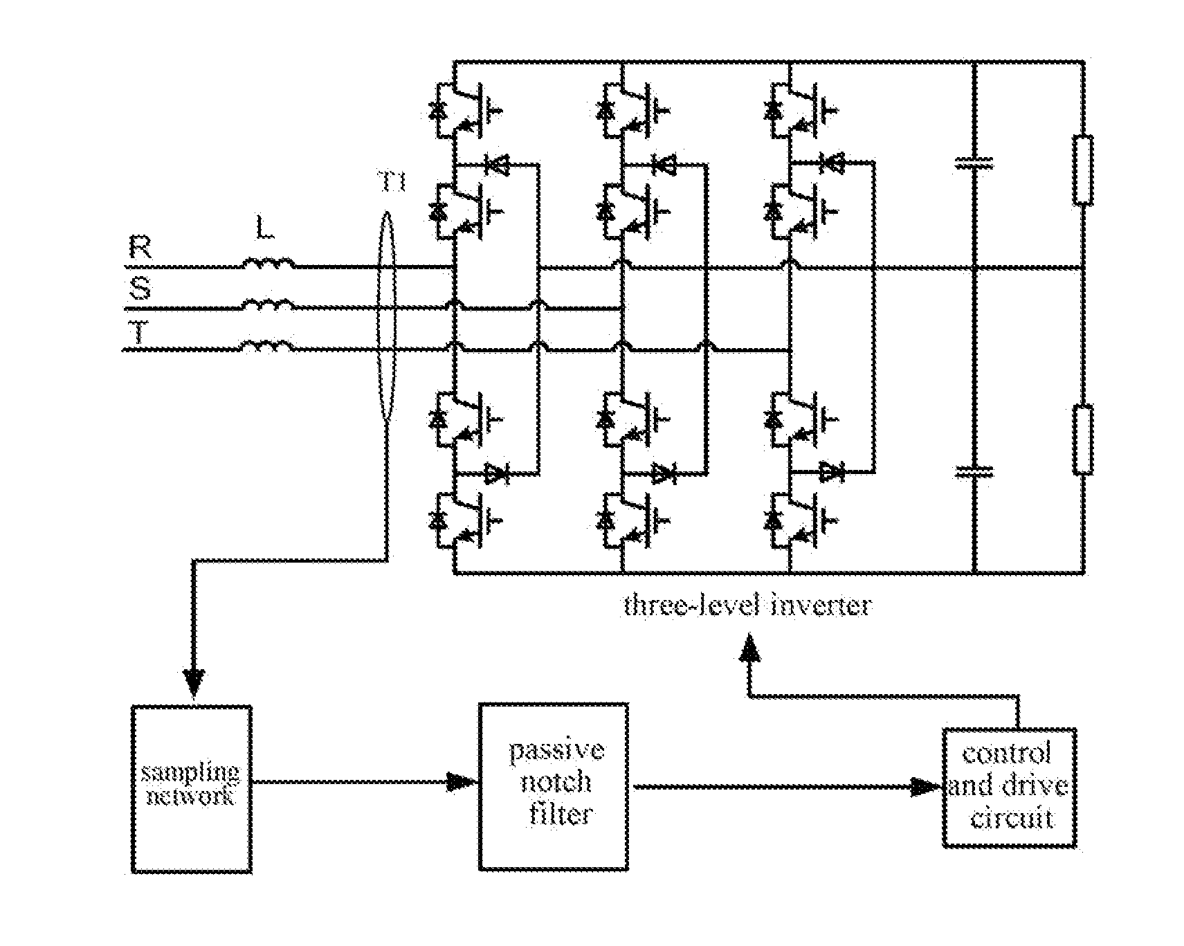
[0037]Please refer to the schematic diagram of the feedback control circuit shown in FIG. 8. FIG. 8 illustrates an example in which the power converter controlled by the feedback control circuit is an inverter, and the sampling network in the feedback control circuit samples the output of the inverter. Compared to the feedback control circuit as shown in FIG. 7, more specifically, the filtering network of the feedback control circuit shown in FIG. 8 is a passive notch filter. Other parts of the feedback control circuit are the same as those shown in FIG. 7, thus no repetitious details for those parts is given herein.
[0038]By means of rational design on parameters of the passive notch filter, the passive notch filter may provide greater attenuation to the ripple signal at the preset frequency and smaller phase delay, while it dose not have impact on the amplitude and phase of signals at other frequency bands. In this embodiment, the ripple signal at the preset frequency is a ripple s...
second embodiment
[0041]The second embodiment of a feedback control circuit is shown in FIG. 11. The components in the second embodiment are similar to that in the first embodiment, whereas the difference therebetween lies in that the filtering network in the feedback control circuit shown in the second embodiment is an active band-stop filter. Other parts of the feedback control circuit are the same as those shown in FIG. 7, thus no repetitious details for those parts will be given here. According to the characteristics of the active band-stop filter, the ripple signal at the preset frequency to be filtered out by this filter is the ripple signals at the switching level frequency and at frequencies close to the switching level frequency, while the sampled signals outside the stop band remain.
[0042]The stopband bandwidth of the active band-stop filter covers a range within which the ripple signals at the switching level frequency and at frequencies close to the switching level frequency fall. Please ...
third embodiment
[0044]FIG. 14 shows the third embodiment of the feedback control circuit. The filtering network in the feedback control circuit shown in FIG. 14 is a digital notch filter. The digital notch filter is implemented by a technical process or method of converting a sampled signal or a series of values into another series of values. During design process of the digital notch filter, it is feasible to design an analog notch filter firstly, and then convert the analog notch filter into a digital notch filter with such as bilinear variational method.
[0045]The digital notch filter may be an IIR (infinite impulse response) digital filter or a FIR (finite impulse response) digital filter. Usually a digital notch filter comprises a digital band-stop filter unit, and the stopband bandwidth of the digital band-stop filter unit covers a range within which the ripple signal at the preset frequency falls. The ripple signal at the preset frequency include the ripple signal at the switching level frequ...
PUM
 Abstract
Description
Claims
Application Information
 - Generate Ideas
- Intellectual Property
- Life Sciences
- Materials
- Tech Scout
- Unparalleled Data Quality
- Higher Quality Content
- 60% Fewer Hallucinations
Browse by: Latest US Patents, China's latest patents, Technical Efficacy Thesaurus, Application Domain, Technology Topic, Popular Technical Reports.
© 2025 PatSnap. All rights reserved.Legal|Privacy policy|Modern Slavery Act Transparency Statement|Sitemap|About US| Contact US: help@patsnap.com