Aircraft ice protection system and method

a technology for aircraft engines and ice protection systems, applied in the field of aircraft engine surface anti-icing and deicing systems, can solve the problems of high cost of chemical de-icing agents, inability to operate continuously, and excessive energy required for de-icing and anti-icing operations on large aircraft engines, and achieve the effect of improving heat transfer

Active Publication Date: 2014-01-16
MRA SYST LLC +1
View PDF29 Cites 44 Cited by
  • Summary
  • Abstract
  • Description
  • Claims
  • Application Information

AI Technical Summary

Benefits of technology

[0008]The present invention provides a system and method for ice protection of aircraft engine surfaces capable ...

Problems solved by technology

A drawback of such systems is that they may require excessive energy for de-icing and continuous anti-icing operation on large aircraft engines, such as high-bypass turbofan engines of the type represented in FIG. 1.
Notable disadvantages of weeping systems include the high cost of chemical de-ici...

Method used


Image

  • Aircraft ice protection system and method
  • Aircraft ice protection system and method
  • Aircraft ice protection system and method

Examples


Embodiment Construction

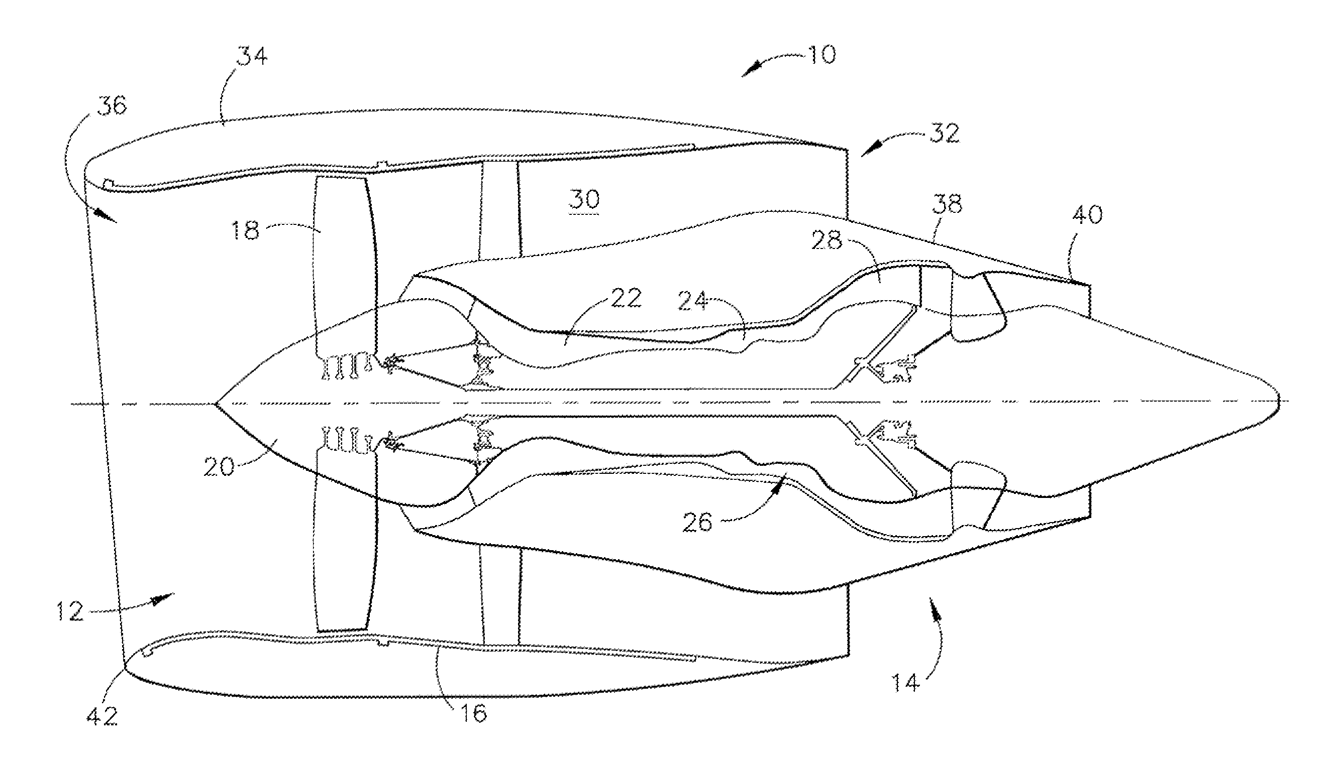
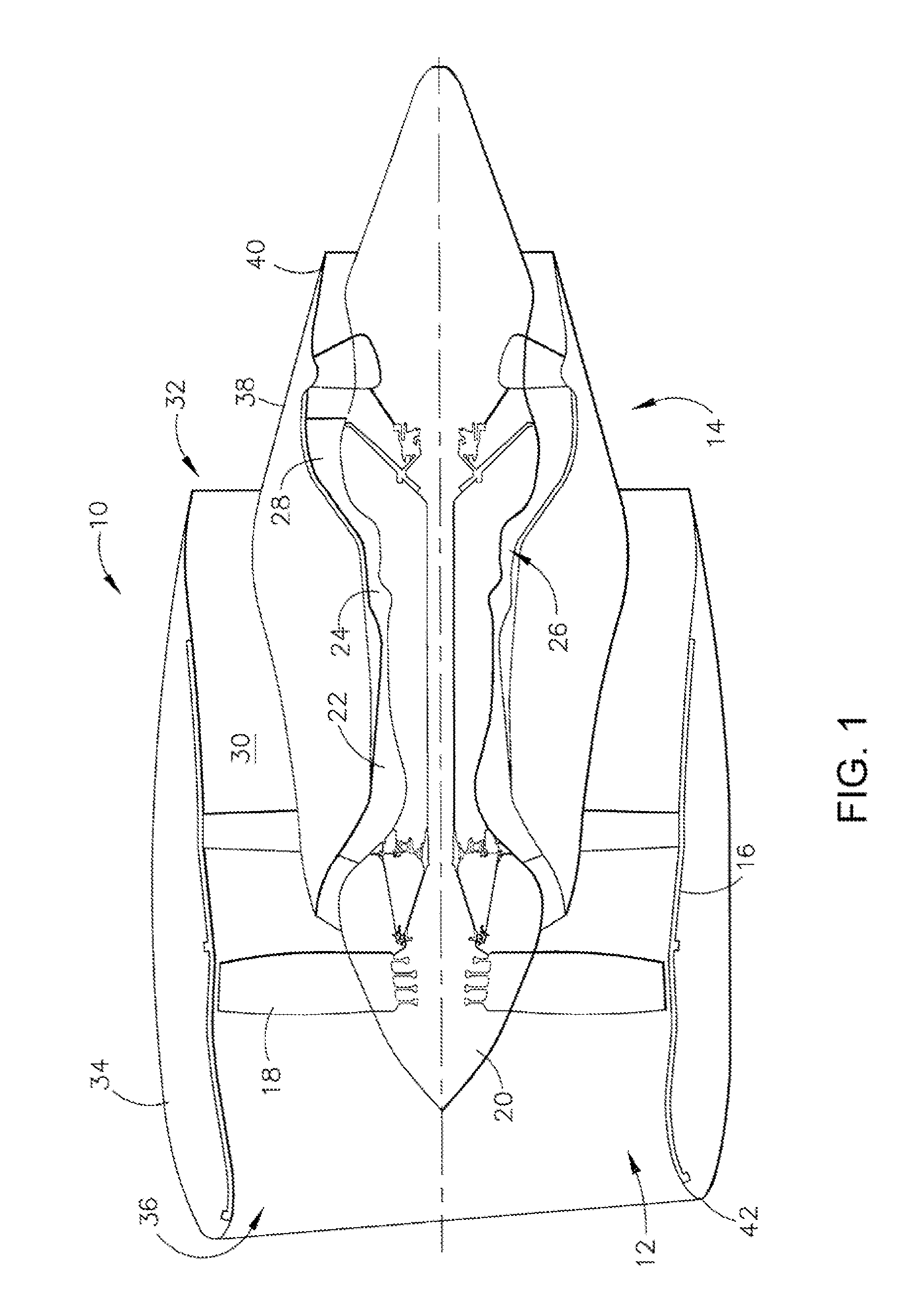
[0019]The present invention is generally applicable to components that operate within relatively low temperatures environments that cause the components to be susceptible to detrimental accumulations of ice. While various applications are foreseeable and possible, applications of particular interest include those that require relatively light-weight components, for example, components of aircraft gas turbine engines. Of particular interest are fan nacelles of high-bypass turbofan engines such as represented in, for example, in FIG. 1.

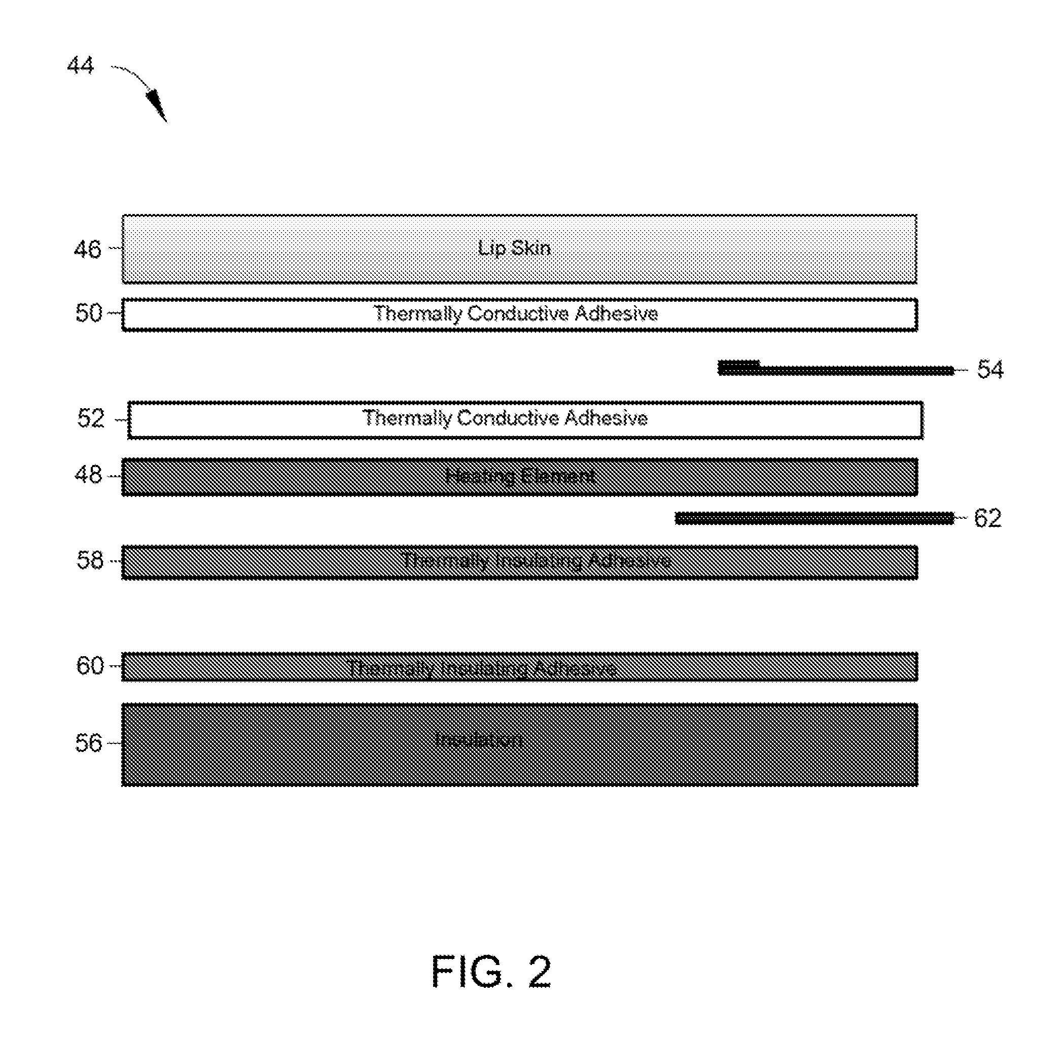
[0020]FIG. 2 represents the cross-section of a heating element architecture 44 suitable for use in ice protection systems, for example, ice protection systems 70 shown in FIG. 3 through 6 in accordance with certain embodiments of the present invention. FIG. 2 also represents a lip skin 46 of a nacelle inlet lip, for example, the inlet lip 42 of FIG. 1. As such, the lip skin 46 is not part of the heating element architecture 44 and is shown only for clar...


PUM

PropertyMeasurementUnit
Thicknessaaaaaaaaaa
Poweraaaaaaaaaa
Densityaaaaaaaaaa

Abstract

A system and method for ice protection of a component, wherein the system is adapted to be adhesively bonded to a surface of the component. The system includes a heating element layer, at least one thermally conductive adhesive layer that adhesively bonds a first side of the heating element layer to the component, an insulation layer, at least one thermally insulating adhesive layer that adhesively bonds a second side of the heating element to the insulation layer, an electrical bus bar adapted to provide a connection between a power supply and the heating element layer, and at least one temperature sensor.

Description

CROSS REFERENCE TO RELATED APPLICATIONS[0001]This application claims the benefit of U.S. Provisional Application No. 61 / 671,218, filed Jul. 13, 2012, the contents of which are incorporated herein by reference.BACKGROUND OF THE INVENTION[0002]The present invention generally relates to turbomachinery, and more particularly to anti-icing and de-icing systems for aircraft engine surfaces.[0003]FIG. 1 schematically represents a high-bypass turbofan engine 10 of a type known in the art. The engine 10 is schematically represented as including a fan assembly 12 and a core engine 14. The fan assembly 12 is shown as including a composite fan casing 16 and a spinner nose 20 projecting forward from an array of fan blades 18. Both the spinner nose 20 and fan blades 18 are supported by a fan disc (not shown). The core engine 14 is represented as including a high-pressure compressor 22, a combustor 24, a high-pressure turbine 26 and a low-pressure turbine 28. A large portion of the air that enters...

Claims


Application Information

Patent Timeline
IPC IPC(8): B64D15/12
CPCB64D15/12Y10T156/10Y10T156/1052B64D15/14
Inventor CALDER, DAVID PATRICKOPIFICIUS, JULIAN ALEXANDERPEDERSON, ERIK THOMASFLOSDORF, DAVID CENIT
Owner MRA SYST LLC
Why Eureka
Try Eureka