

Truck Body For Mining Vehicle
- Summary
- Abstract
- Description
- Claims
- Application Information
AI Technical Summary
Benefits of technology
Problems solved by technology
Method used
Image

Examples
Embodiment Construction
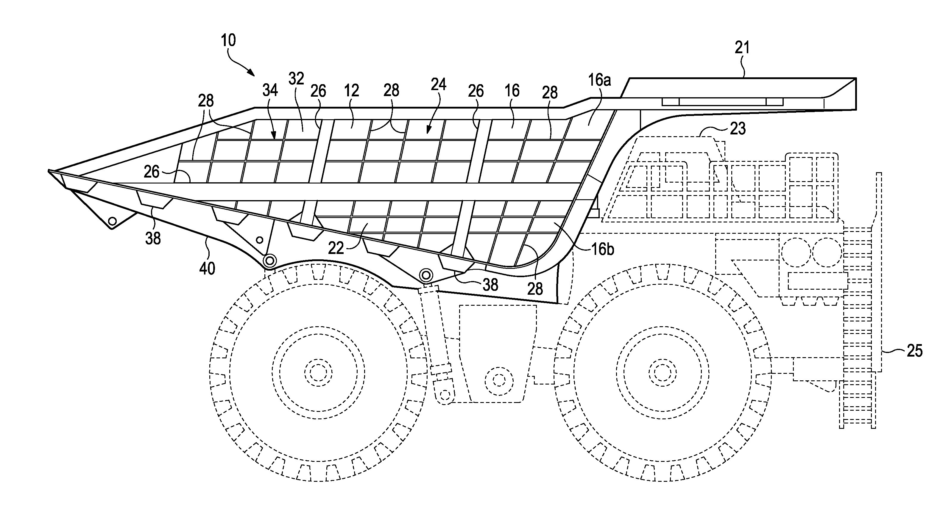
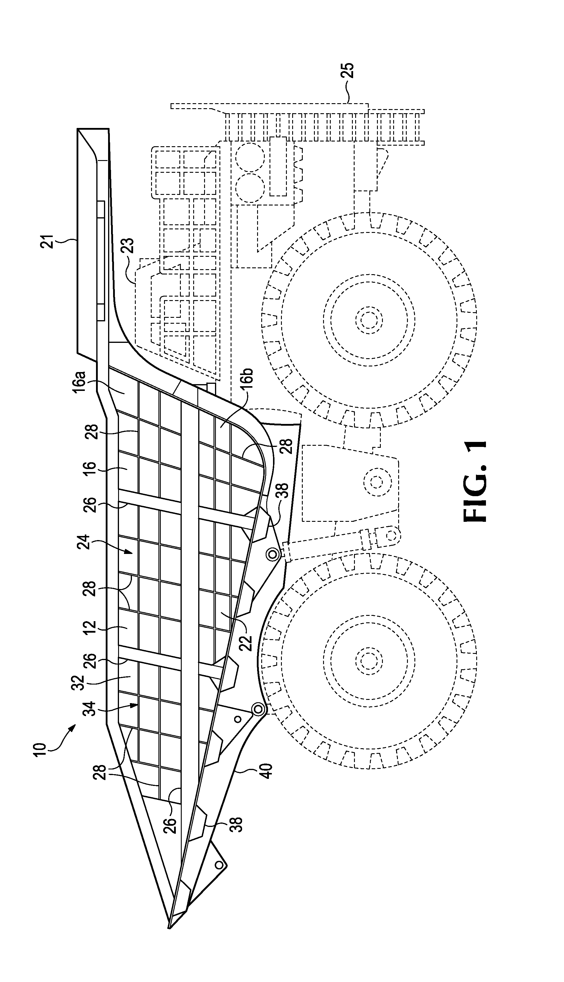
[0020]The present invention pertains to a truck body for use with a mining dump truck that enables a larger load of mined material to be transported in a single haul cycle. The provision of a larger hauled load results in a substantial increase in the efficiency of the mining operation and reduced costs. Mining trucks are off-road vehicles preferably with payload capacities greater than 90 metric tons, but smaller payload capacities are possible.
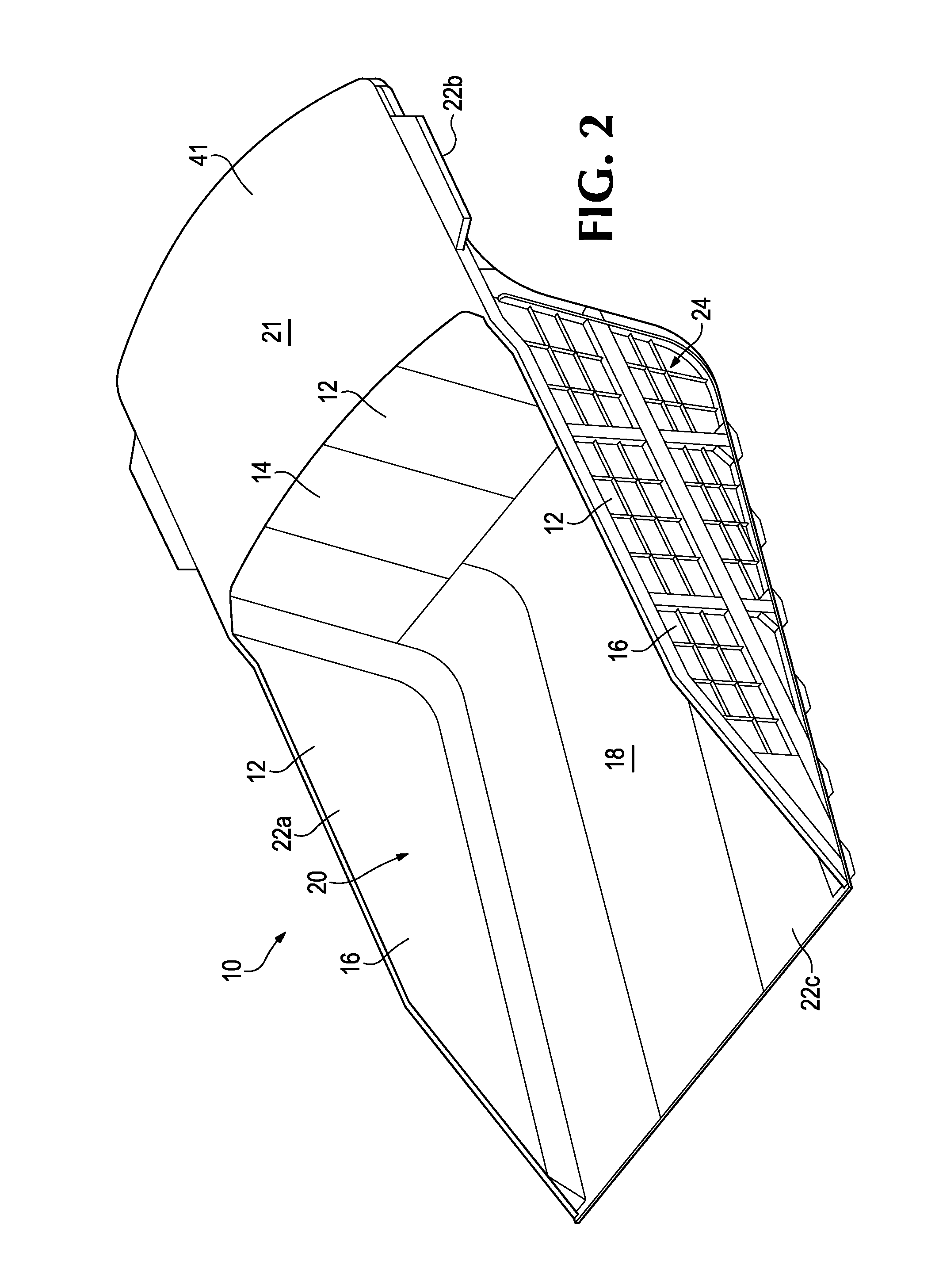
[0021]In accordance with one embodiment of the present invention, a truck body 10 is defined by a plurality of containment walls 12, including a front wall 14 and a pair of sidewalls 16, and a floor 18 that are joined together along edges to collectively define a hauling cavity 20 in which the mined material is received and carried. The truck body is pivotally mounted to a wheeled frame 25 that includes a cab 23 for the operator. A cover 21 extends forward over the cab 23 to protect it. Once the mined material is transported to its destinati...
PUM
 Abstract
Description
Claims
Application Information