Hardware-in-the-loop grid simulator system and method

Inactive Publication Date: 2014-01-16
CLEMSON UNIVERSITY
View PDF1 Cites 49 Cited by
  • Summary
  • Abstract
  • Description
  • Claims
  • Application Information

AI Technical Summary

Benefits of technology

[0032]Yet further objectives are accomplished by providing an improved isolation transformer to provide more flexibility in fault testing for such systems. More specifically, an improved isolation transformer is provided for isolating zero-sequence current from either a primary or secondary winding in a transformer

Problems solved by technology

In another embodiment, staged parallel-connected reactors

Method used


Image

  • Hardware-in-the-loop grid simulator system and method
  • Hardware-in-the-loop grid simulator system and method
  • Hardware-in-the-loop grid simulator system and method

Examples


Embodiment Construction

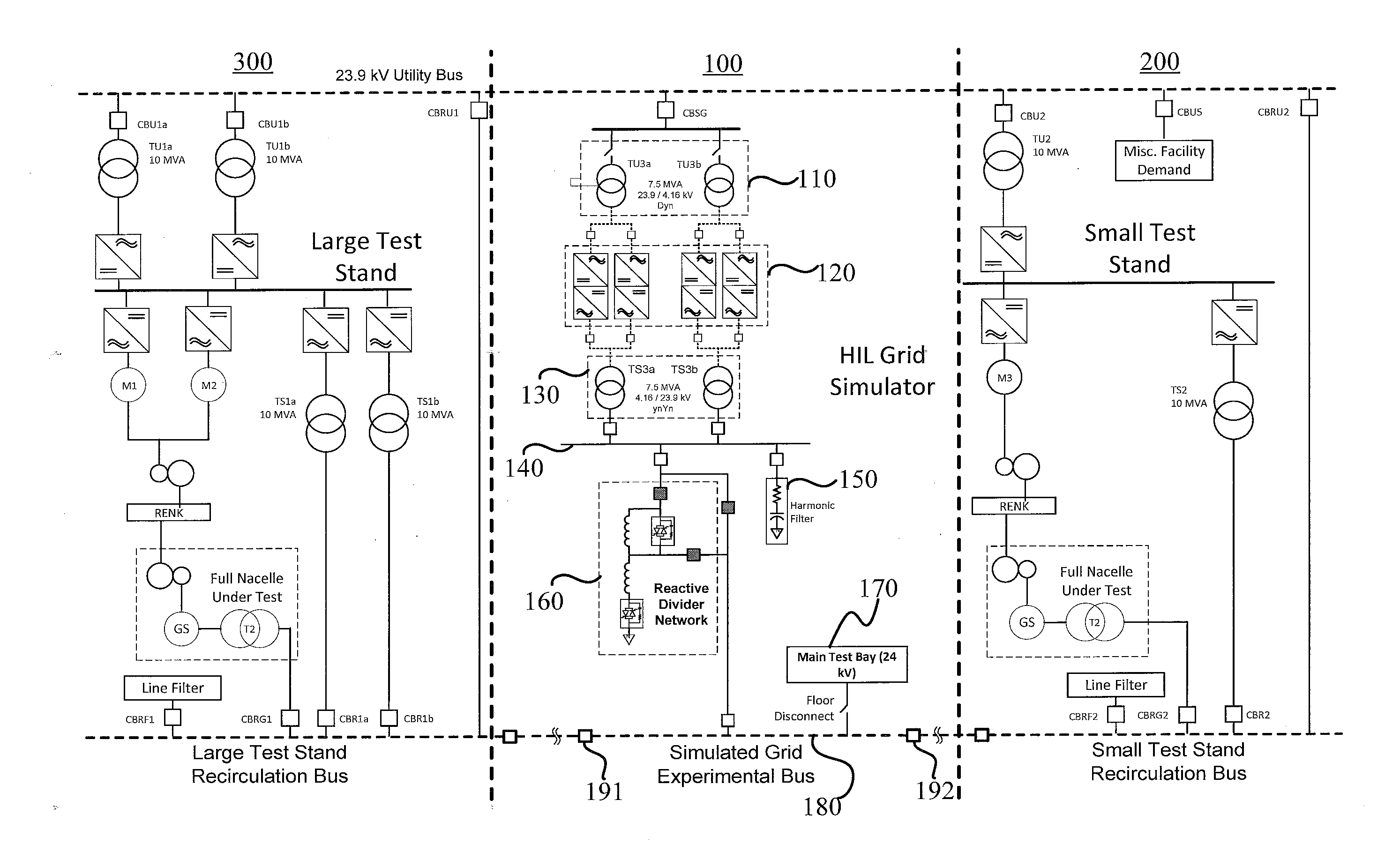
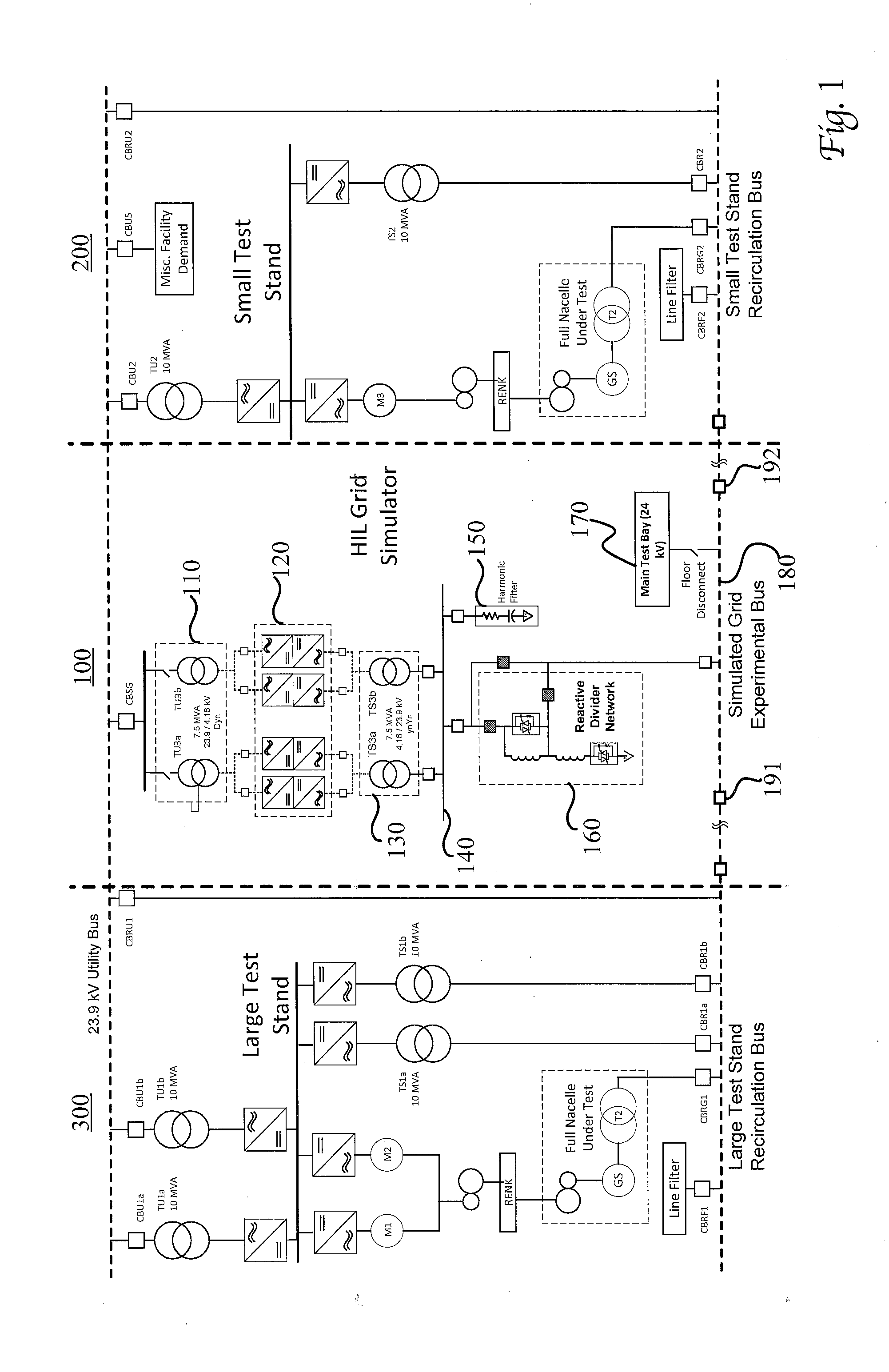
[0045]The invention is perhaps better understood with reference to the drawings attached hereto. Referring now to FIG. 1, an embodiment of a HIL grid simulator 100 is illustrated as connected to a small test stand 200 and a large test stand 300. The utility side transformer(s) portion 110 is attached to the variable frequency drive 120, which is in turn connected to the simulated grid side transformer(s) 130. The power amplifier bus 140 connects to a harmonic filter 150, the reactive divider network 160, and the simulated grid side transformer(s) 130. A simulated grid experimental bus 180 connects to a main test bay 170. The simulated grid 180 electrically connects to the small test stand 200 through breaker 192 and to large test stand 300 through breaker 191. The simulated grid bus 180 is capable of being connected to bus 140 either through the reactive divider network 160 or through a bypass breaker directly connecting bus 180 to bus 140. It is at the simulated grid bus 180 that a...


PUM


Abstract

A hardware-in-the-loop (HIL) electrical grid simulation system and method that combines a reactive divider with a variable frequency converter to better mimic and control expected and unexpected parameters in an electrical grid. The invention provides grid simulation in a manner to allow improved testing of variable power generators, such as wind turbines, and their operation once interconnected with an electrical grid in multiple countries. The system further comprises an improved variable fault reactance (reactive divider) capable of providing a variable fault reactance power output to control a voltage profile, therein creating an arbitrary recovery voltage. The system further comprises an improved isolation transformer designed to isolate zero-sequence current from either a primary or secondary winding in a transformer or pass the zero-sequence current from a primary to a secondary winding.

Description

CROSS-REFERENCE TO RELATED APPLICATIONS[0001]This application claims priority to pending U.S. Provisional Application No. 61 / 672,133 filed Jul. 16, 2012, which is incorporated herein by reference.BACKGROUND OF THE INVENTION[0002]The invention relates to an electrical grid simulation system and, more particularly, to an improved system and method for grid simulation that combines a reactive divider with a variable frequency converter to better mimic and control both expected and unexpected parameters in an electrical grid. The invention provides grid simulation in a manner that allows improved testing of variable power generators—such as wind turbines, solar inverters, energy storage devices, and power conditioning equipment (such as STATCOMS)—and their operation once interconnected within an electrical grid in multiple countries. Further, this invention enables improved testing of power generation devices for use in multiple countries with varying voltages, frequencies, and other op...

Claims


Application Information

Patent Timeline
IPC IPC(8): G01R31/40
CPCG01R31/40G01R19/2513H02S50/10Y02E10/50
Inventor FOX, JOHN CURTISSCOLLINS, JR., EDWARD RANDOLPHRIGAS, NIKOLAOS
Owner CLEMSON UNIVERSITY
Why Eureka
Try Eureka