Relay-welding detection circuit and power supplying system

a detection circuit and relay technology, applied in relays, electric devices, instruments, etc., can solve problems such as current flowing from a quick charger to the welding detection circuit, and achieve the effect of high impedan

Active Publication Date: 2014-01-16
PANASONIC INTELLECTUAL PROPERTY MANAGEMENT CO LTD
View PDF5 Cites 22 Cited by
  • Summary
  • Abstract
  • Description
  • Claims
  • Application Information

AI Technical Summary

Benefits of technology

[0010]According to the present invention, it is possible to provide a relay welding detection circu...

Problems solved by technology

In the related art, when the input-side impedance of the relay welding detection circuit is not a predetermined value (for e...

Method used


Image

  • Relay-welding detection circuit and power supplying system
  • Relay-welding detection circuit and power supplying system
  • Relay-welding detection circuit and power supplying system

Examples


embodiment 1

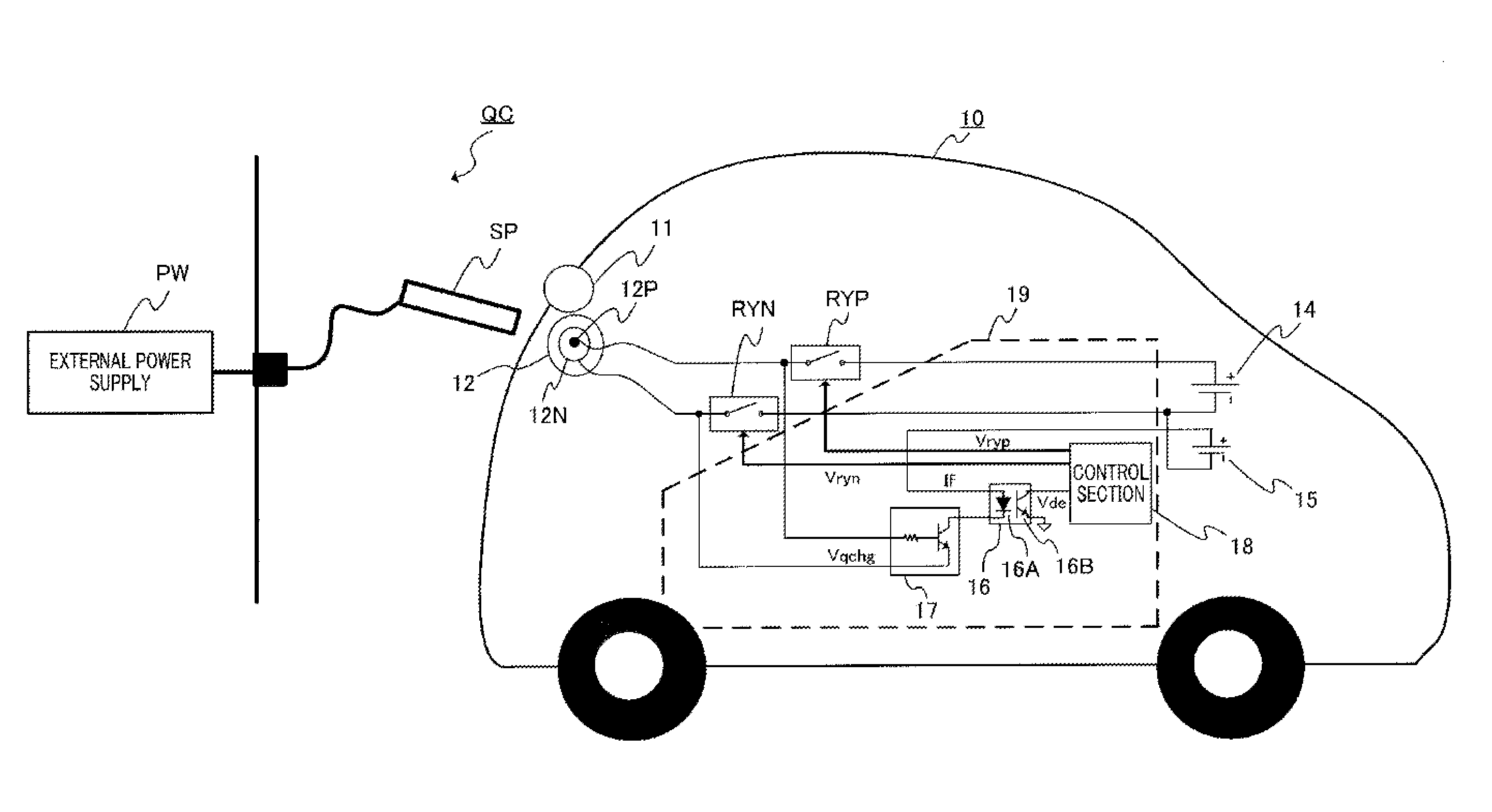
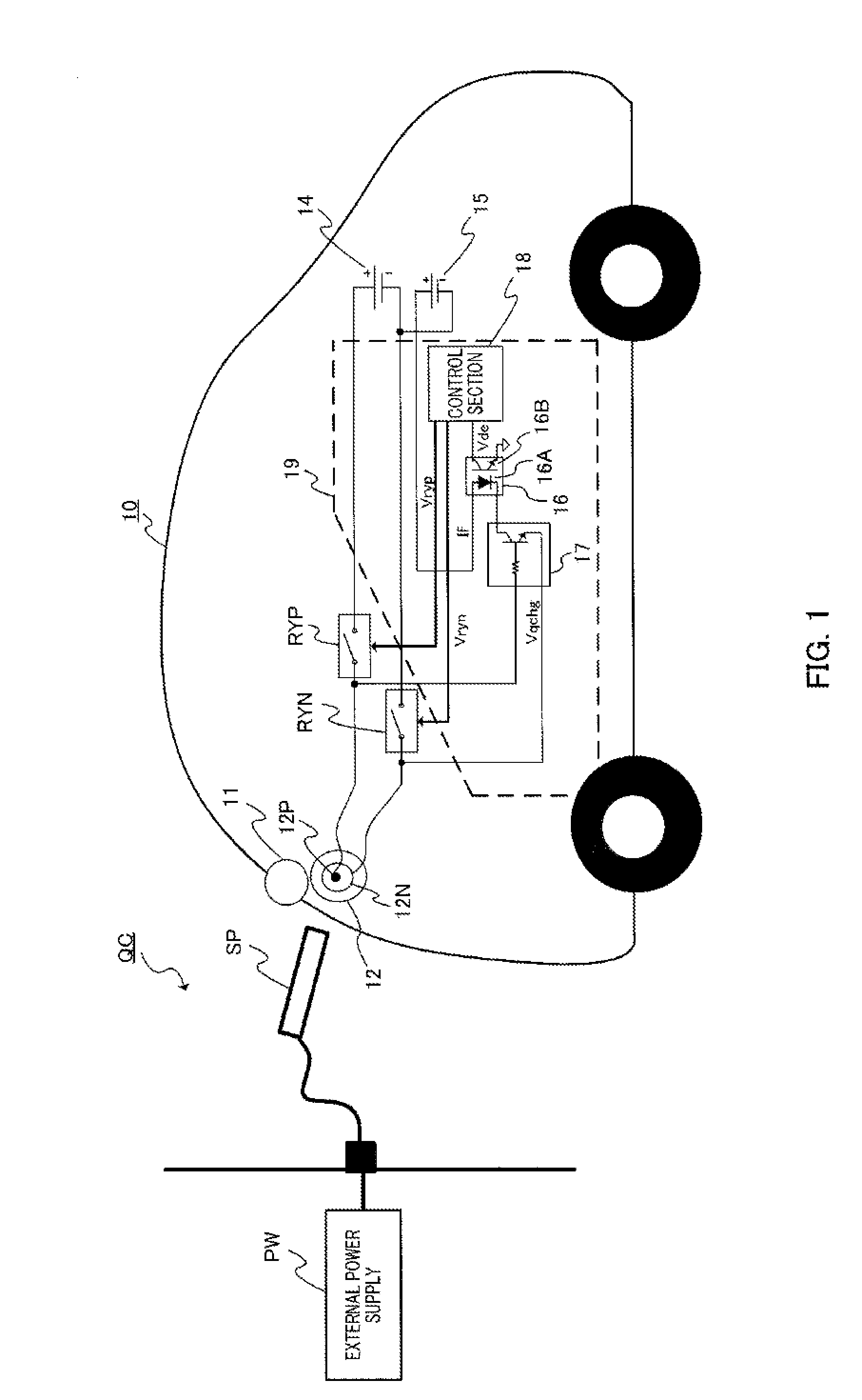
[0018]FIG. 1 is a diagram illustrating the schematic structure of a power supply system of an electric vehicle according to Embodiment 1.

[0019]Charging terminal 12 is provided in body 10 of the electric vehicle. Cover 11 is provided in charging terminal 12. When charging is not performed, cover 11 is closed and charging terminal 12 is shielded from the outside. When charging is performed, cover 11 is opened. During charging, power is supplied from external power supply PW to charging terminal 12 through power supply plug SP.

[0020]A positive (+) terminal of first battery 14 for supplying power to a vehicle driving motor is connected to power supply-side terminal 12P of charging terminal 12 through power supply-side relay RYP.

[0021]Ground-side terminal 12N of charging terminal 12 is connected to a negative (−) terminal of the first battery through ground-side relay RYN.

[0022]In addition, a negative terminal of second battery 15 (power supply section) for supplying power to in-vehicle ...

embodiment 2

[0052]FIG. 4 is a diagram illustrating the schematic structure of a power supply system of an electric vehicle according to Embodiment 2. In FIG. 4, the same components as those in FIG. 1 are denoted by the same reference numerals.

[0053]A positive terminal of battery 14 for supplying power to a vehicle driving motor is connected to power supply-side terminal 12P of charging terminal 12 of electric vehicle 10 through power supply-side relay RYP. Ground-side terminal 12N of charging terminal 12 is connected to a negative terminal of battery 14 through ground-side relay RYN.

[0054]In addition, one terminal of capacitor (power supply section) C for supplying power to in-vehicle accessories is connected to power supply-side terminal 12P of charging terminal 12 through current-limiting resistor R. Ground-side terminal 12N of charging terminal 12 is connected to the other terminal of capacitor C.

[0055]A collector of phototransistor 20B forming second photocoupler 20 is connected to a connec...


PUM


Abstract

The relay-welding detection circuit detects welding of relays (RYP, RYN) provided on a charging path from an external power supply (PW) to a first battery (14), and is provided with: a second battery (15) that can supply a welding-detection power supply independently of the external power supply (PW); a transistor switch (17) that is a circuit in which there is substantially zero current flowing in from the external power supply (PW) side of the relays, and that controls whether or not to supply the welding-detection power supply to the second battery (15) on the basis of the voltage at the external power supply (PW) side of the relays; and a control unit (18) that is electrically insulated from the transistor switch (17), and that to detects welding of the relays (RYP, RYN) on the basis of whether or not the transistor switch (17) has supplied the welding-detection power supply.

Description

TECHNICAL FIELD[0001]The present invention relates to a relay welding detection circuit, and more particularly, to a relay welding detection circuit for detecting the welding of a relay which is used for a charging circuit for charging a battery of, for example, an electric vehicle and a power supply system including the relay welding detection circuit.BACKGROUND ART[0002]A relay circuit for connecting and disconnecting a quick charger to and from a battery connecting junction circuit during charging has been used in a charging circuit of an electric vehicle. A mechanical relay contact (hereinafter, abbreviated to a relay) is used in the relay circuit, and the relay is turned on and off and is welded when a high voltage is applied and a large amount of current flows. A relay welding detection circuit for detecting the welding of the relay has been known (for example, see Patent Literature 1).[0003]In the related art, when the input-side impedance of the relay welding detection circu...

Claims


Application Information

Patent Timeline
IPC IPC(8): H02H3/20
CPCH02H3/20B60L3/0023B60L53/14G01R31/3278H01H1/0015H01H47/002Y02T10/70Y02T10/7072Y02T90/14Y02T90/12
Inventor TAZAKI, SHINTARO
Owner PANASONIC INTELLECTUAL PROPERTY MANAGEMENT CO LTD
Why Eureka
Try Eureka