
Firearm noise suppressor system

a technology for suppressing system and firearm, which is applied in the direction of muzzle attachment, weapon components, weapons, etc., can solve the problems of complex baffle structure, undesirable “ringing” tone to be emitted, and failure to provide several needed features, etc., to achieve the effect of enhancing the reduction of sound and flash

Active Publication Date: 2014-01-23
SILENCERCO
View PDF0 Cites 34 Cited by
  • Summary
  • Abstract
  • Description
  • Claims
  • Application Information

AI Technical Summary

Benefits of technology

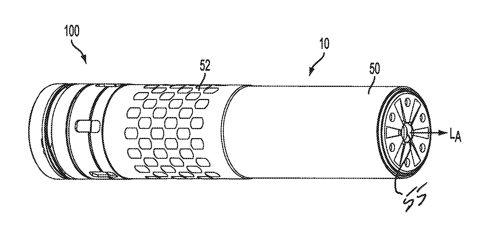
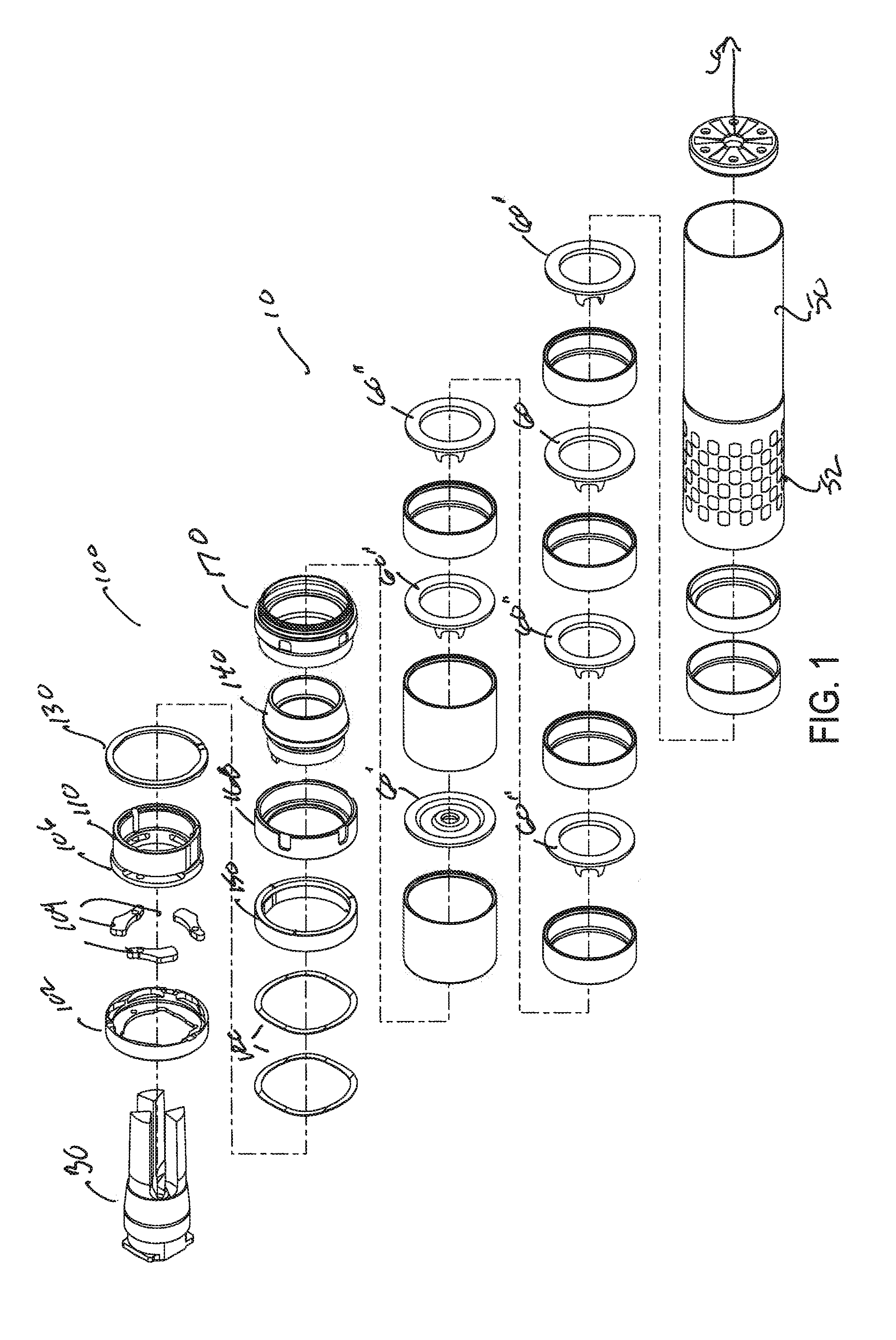
The noise suppressor is designed to reduce sound and flash caused by the discharge of a firearm. It uses baffles that have several features to improve its effectiveness. These features include a conical section with a central bore for the projectile to pass through, a second conical section with shoulder elements to create turbulence in the gas stream, and a gas cross-flow aperture to direct a perpendicular gas jet onto the discharge gas stream. These features work together to suppress the noise and flash caused by the firearm discharge.

Problems solved by technology

The aforementioned designs fail to provide several needed features necessary and desirable for today's firearms.
's flash suppressor, the design of the respective tines of the flash suppressor results in an undesirable “ringing” tone to be emitted from the flash suppressor upon the discharge of the firearm due to imparted harmonics on the respective tines of the firearm.
Quite complex baffle structures are known in the prior art.
However, while such a modified “K” baffle worked well with pistol caliber firearms, the asymmetry caused some detrimental effect on accuracy when used with rifle caliber firearms, and required an increase in the size of the bore aperture of the baffle to ensure minimization of bullet yaw.
This would otherwise result in projectiles striking the baffles and the end cap of the suppressor.

Method used


Image

  • Firearm noise suppressor system
  • Firearm noise suppressor system
  • Firearm noise suppressor system

Examples


Embodiment Construction

[0030]Embodiments of the present invention can be understood more readily by reference to the following detailed description, examples, drawing, and claims, and their previous and following description. However, before the present devices, systems, and / or methods are disclosed and described, it is to be understood that embodiments described herein are not limited to the specific devices, systems, and / or methods disclosed unless otherwise specified, as such can, of course, vary. It is also to be understood that the terminology used herein is for the purpose of describing particular aspects only and is not intended to be limiting.

[0031]The following description is provided as an enabling teaching of the invention in its best and currently known embodiments. To this end, those skilled in the relevant art will recognize and appreciate that many changes can be made to the various aspects of the invention described herein, while still obtaining the beneficial results of the described embo...


PUM

PropertyMeasurementUnit
compressiveaaaaaaaaaa
compressive resistanceaaaaaaaaaa
massaaaaaaaaaa

Abstract

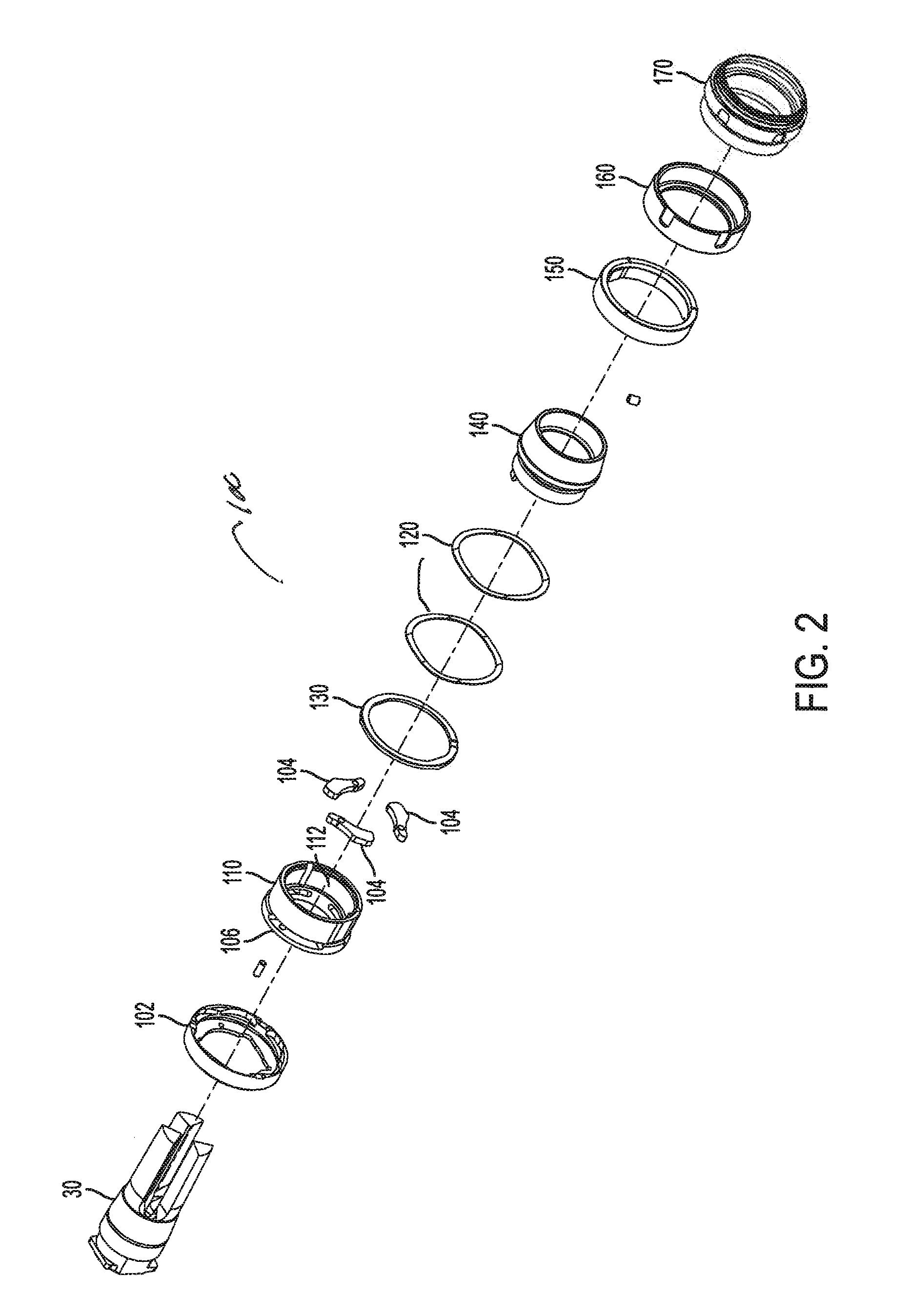
A noise suppressor system for attachment to a firearm including a barrel having a longitudinal axis. The noise suppressor system including the combination of: a flash suppressor adapted to be attached to the muzzle of the barrel coaxially therewith, a noise suppressor including a proximal mount assembly having a bore for coaxially receiving the flash suppressor, and a means for selectively securely coupling the noise suppressor system to the firearm.

Description

FIELD OF THE INVENTION[0001]The present invention relates to a noise suppressor for a firearm, and more particularly to flash suppressors and baffles for use in a noise suppressor for a firearm and to systems for removably attaching the noise suppressor or other auxiliary device to the muzzle of a firearm barrel.BACKGROUND OF THE INVENTION[0002]Noise suppressors for firearms are well known in the prior art, and many have been patented over a considerable period of time. Many different techniques have been developed and patented, and flash suppressors and baffles of varying designs have been extensively used. The aim and intention of a noise suppressor, regardless of the technique used, is to reduce the pressure and velocity of the propellant gases from the sound suppressor so that the resulting sound level is significantly reduced.[0003]Prior art noise suppressors include flash suppressor systems and internal baffles for reducing the muzzle flash of a firearm with it has been discha...

Claims


Application Information

Patent Timeline
Patent Type & Authority Applications(United States)
IPC IPC(8): F41A21/30F41A21/32
CPCF41A21/30F41A21/325F41A21/34Y10T29/49826
Inventor SHULTS, JONATHON
Owner SILENCERCO
Learn More