Color imaging element, imaging device, and storage medium storing an imaging program

a technology of color imaging and image pickup, which is applied in the field of color image pickup devices, imaging apparatuses and imaging programs, can solve the problems of low sensitivity and inability to treat normal pixels in the same way, and achieve the effect of raising the interpolation precision of phase difference detection pixels

Inactive Publication Date: 2014-01-23
FUJIFILM CORP
View PDF0 Cites 13 Cited by
  • Summary
  • Abstract
  • Description
  • Claims
  • Application Information

AI Technical Summary

Benefits of technology

[0037]According to the present invention, the advantageous effect is exhibited of ...

Problems solved by technology

The precision of such AF operation is higher the more there are of the phase difference detection pixels, however during main image capture of a normal subject image, the phase ...

Method used


Image

  • Color imaging element, imaging device, and storage medium storing an imaging program
  • Color imaging element, imaging device, and storage medium storing an imaging program
  • Color imaging element, imaging device, and storage medium storing an imaging program

Examples


first exemplary embodiment

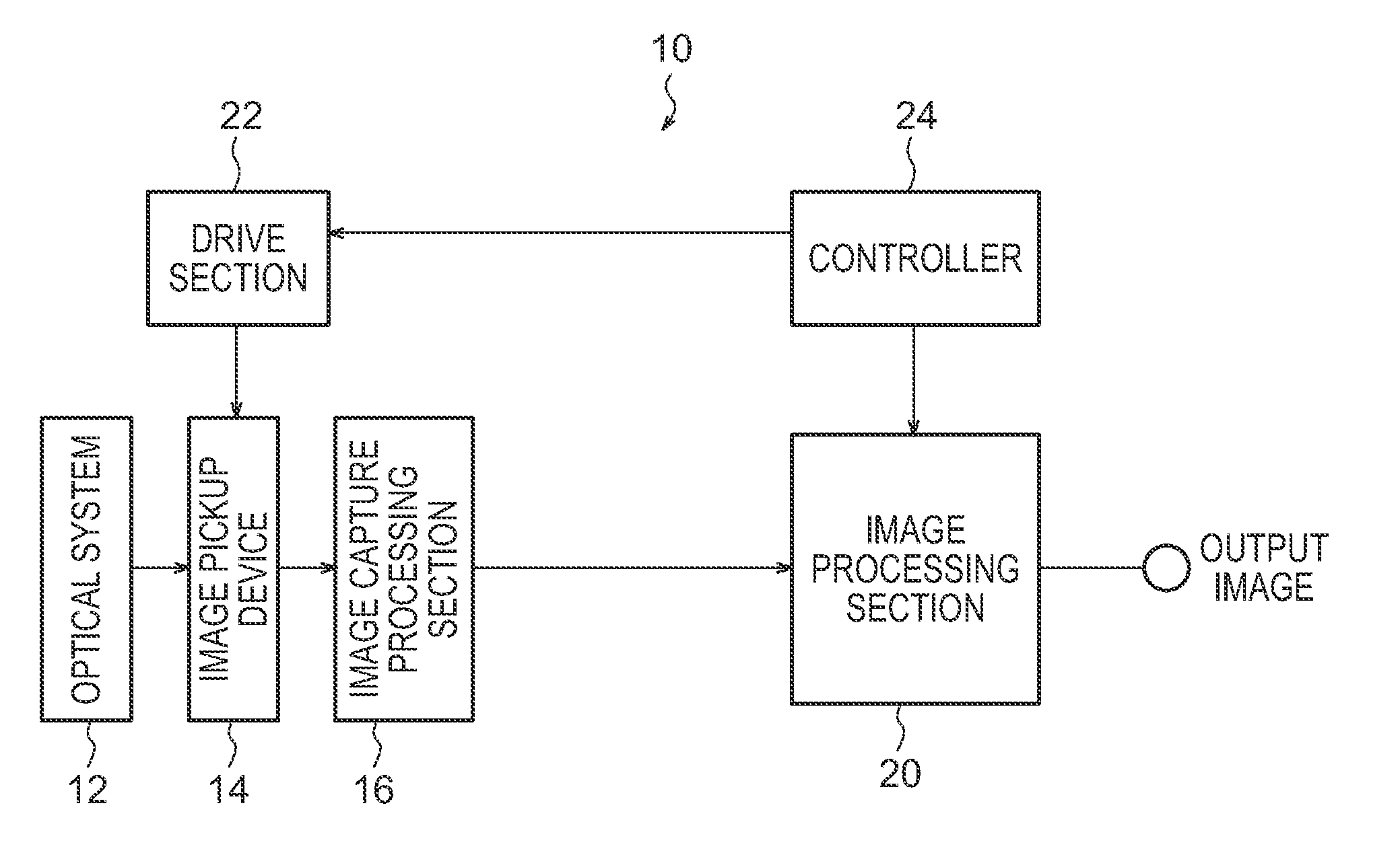
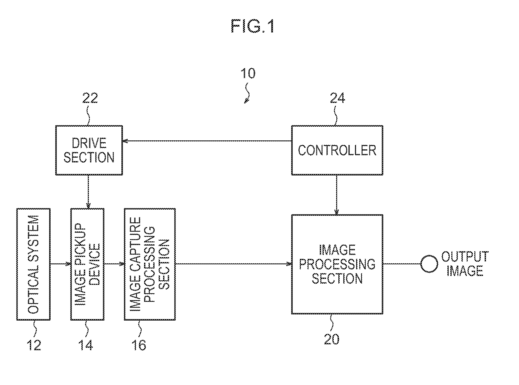
[0054]FIG. 1 is a schematic block diagram illustrating an imaging apparatus 10 according to the present exemplary embodiment. The imaging apparatus 10 is configured including an optical system 12, an image pickup device 14, an image capture processing section 16, an image processing section 20, a drive section 22, and a controller 24.

[0055]The optical system 12 is configured including for example a lens set configured from plural optical lenses, an aperture adjustment mechanism, a zoom mechanism, and an automatic focusing mechanism.

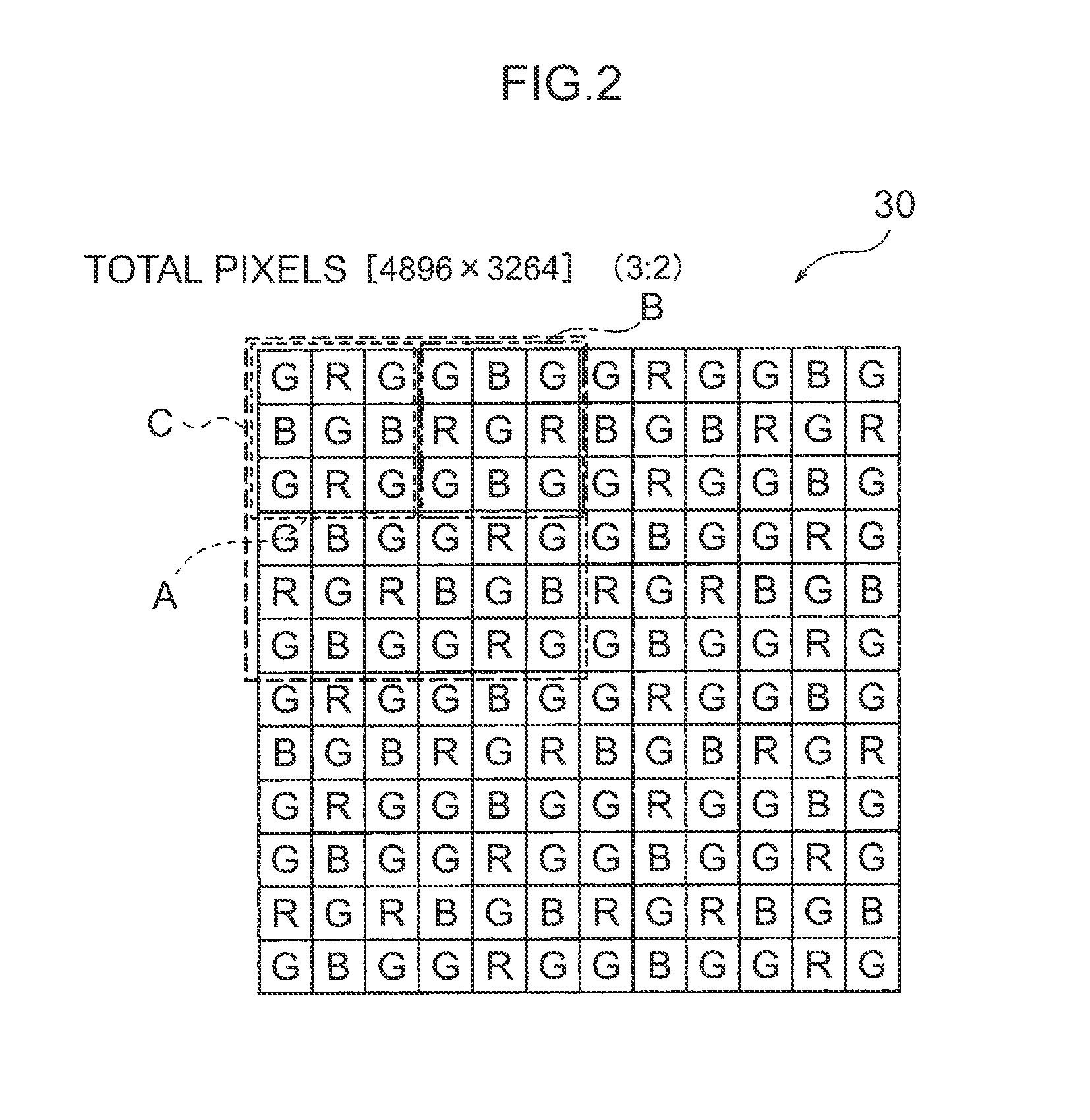
[0056]The image pickup device 14 is what is referred to as a 1-chip image pickup device configured by an image pickup device, such as for example a Charge Coupled Device (CCD) or a Complementary Metal Oxide Semiconductor (CMOS) containing plural photoelectric conversion elements arrayed in the horizontal direction and vertical direction, with a color filter disposed above the image pickup device.

[0057]FIG. 2 illustrates a portion of a color filter 30 acco...

second exemplary embodiment

[0099]Explanation next follows regarding a second exemplary embodiment of the present invention. Note that the same reference numerals are allocated to portions similar to those of the first exemplary embodiment, and detailed explanation thereof is omitted.

[0100]FIG. 6 illustrates a placement of light-blocking films 40A, 40B according to the present exemplary embodiment. A point of difference of the present exemplary embodiment to the first exemplary embodiment is the placement of the light-blocking films 40A, 40B.

[0101]As illustrated in FIG. 6, in the present exemplary embodiment the light-blocking portions 40 are provided in each of a first array pattern A and a second array pattern B of two pairs thereof that configure a basic array pattern C, with horizontal direction array lines of basic array patterns C that are placed with the light-blocking portions 40 alternating in the vertical direction with horizontal direction array lines of basic array patterns C that are not placed wi...

third exemplary embodiment

[0104]Explanation next follows regarding a third exemplary embodiment of the present invention. Note that the same reference numerals are allocated to portions similar to those of the above exemplary embodiment, and detailed description thereof is omitted.

[0105]FIG. 7 illustrates a placement of light-blocking films 40A, 40B according to the present exemplary embodiment. A point of difference of the present exemplary embodiment to the first exemplary embodiment is the placement of the light-blocking films 40A, 40B. Thinning driving is similar to that of the second exemplary embodiment.

[0106]As illustrated in FIG. 7, in the present exemplary embodiment the light-blocking portions 40 are provided in one pair of a first array pattern A and a second array pattern B that are in row in the horizontal direction out of two pairs of the array pattern A and the second array pattern B that configure a basic array pattern C, with horizontal direction array lines of the basic array patterns C tha...


PUM


Abstract

Interpolation precision of phase difference detection pixels is raised. An image sensor (14) is provided with a color filter (30) upon which a basic sequence pattern, formed by disposing a first sequence pattern and a second sequence pattern in point symmetry, is repeatedly disposed. In the first sequence pattern, first filters are disposed on pixels in the four corners and in the center of a square array of 3×3 pixels, second filters are disposed in a horizontal line in the center of a square array, and third filters are disposed in a vertical line in the center of a square array. In the second sequence pattern, the first sequence pattern and the positions of the first filters are the same, while the positions of the second filters and the positions of the third filters have been swapped.

Description

CROSS-REFERENCE TO RELATED APPLICATIONS[0001]This application is a continuation application of International Application No. PCT / JP2011 / 067549, filed Jul. 29, 2011, the disclosure of which is incorporated herein by reference in its entirety. Further, this application claims priority from Japanese Patent Application No. 2011-066631, filed Mar. 24, 2011, and Japanese Patent Application No. 2011-163311, filed Jul. 26, 2011.BACKGROUND[0002]1. Technical Field[0003]The present invention relates to a color image pickup device, an imaging apparatus and an imaging program, and in particular to a color image pickup device that includes phase difference detection pixels and to an imaging apparatus and an imaging program of the same.[0004]2. Related Art[0005]For solid state image pickup devices installed in imaging apparatuses such as digital cameras, there are those that, in order to raise Auto Focus (AF) performance have phase difference detection pixels as a portion of the pixels out of many...

Claims


Application Information

Patent Timeline
IPC IPC(8): H04N5/232
CPCH04N5/23212H04N23/672H04N25/445H04N25/704H04N23/843H04N25/134
Inventor ENDO, HIROSHIHAYASHI, KENKICHIKAWAMURA, NORIKOAOKI, TAKASHIINOUE, KAZUKI
Owner FUJIFILM CORP
Why Eureka
Try Eureka