
Method of controlling a function of a device and system for detecting the presence of a living being

a technology of living beings and functions, applied in the field of controlling the function of a device and a system for detecting the presence of a living being, can solve the problems that the application of photoplethysmography known from the prior art is limited to diagnostics, and achieve the effect of improving the signal to noise ratio of signal components

Inactive Publication Date: 2014-01-23
KONINKLJIJKE PHILIPS NV
View PDF1 Cites 34 Cited by
  • Summary
  • Abstract
  • Description
  • Claims
  • Application Information

AI Technical Summary

Benefits of technology

The patent describes a method for detecting people or people with certain characteristics in an environment using images. The method is unobtrusive because it does not require sensors to be close to a person. The method uses a sequence of images taken at consecutive points in time and selects measurement zones based on image characteristics. The method is able to detect someone's heart rate or respiration rate with high accuracy by analyzing image changes over time. The method can cover the entire environment and is less susceptible to noise. It can also determine if a person is present based on their heart rate or respiration rate. The method can distinguish between different people with similar biometric features. The method can also remove non-periodic disturbances to improve the signal-to-noise ratio.

Problems solved by technology

Applications of photoplethysmography known from the prior art are limited to diagnostics using heart rate and respiration determinations and using imaging.

Method used


Image

  • Method of controlling a function of a device and system for detecting the presence of a living being
  • Method of controlling a function of a device and system for detecting the presence of a living being
  • Method of controlling a function of a device and system for detecting the presence of a living being

Examples


Embodiment Construction

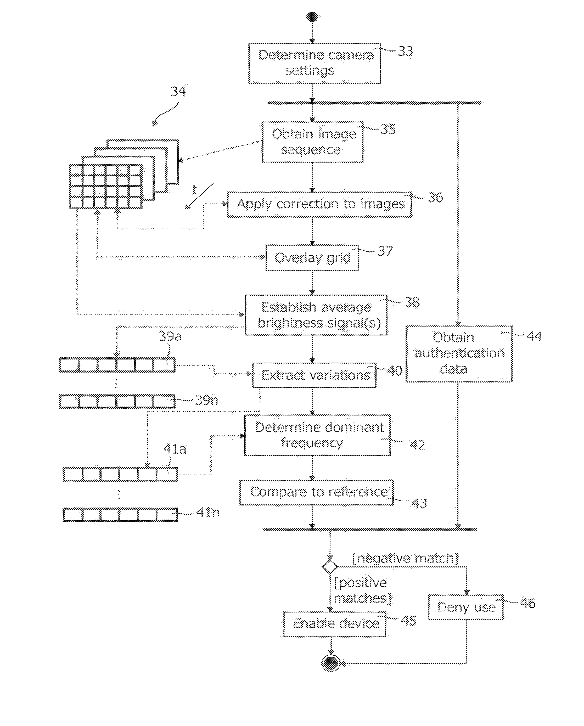
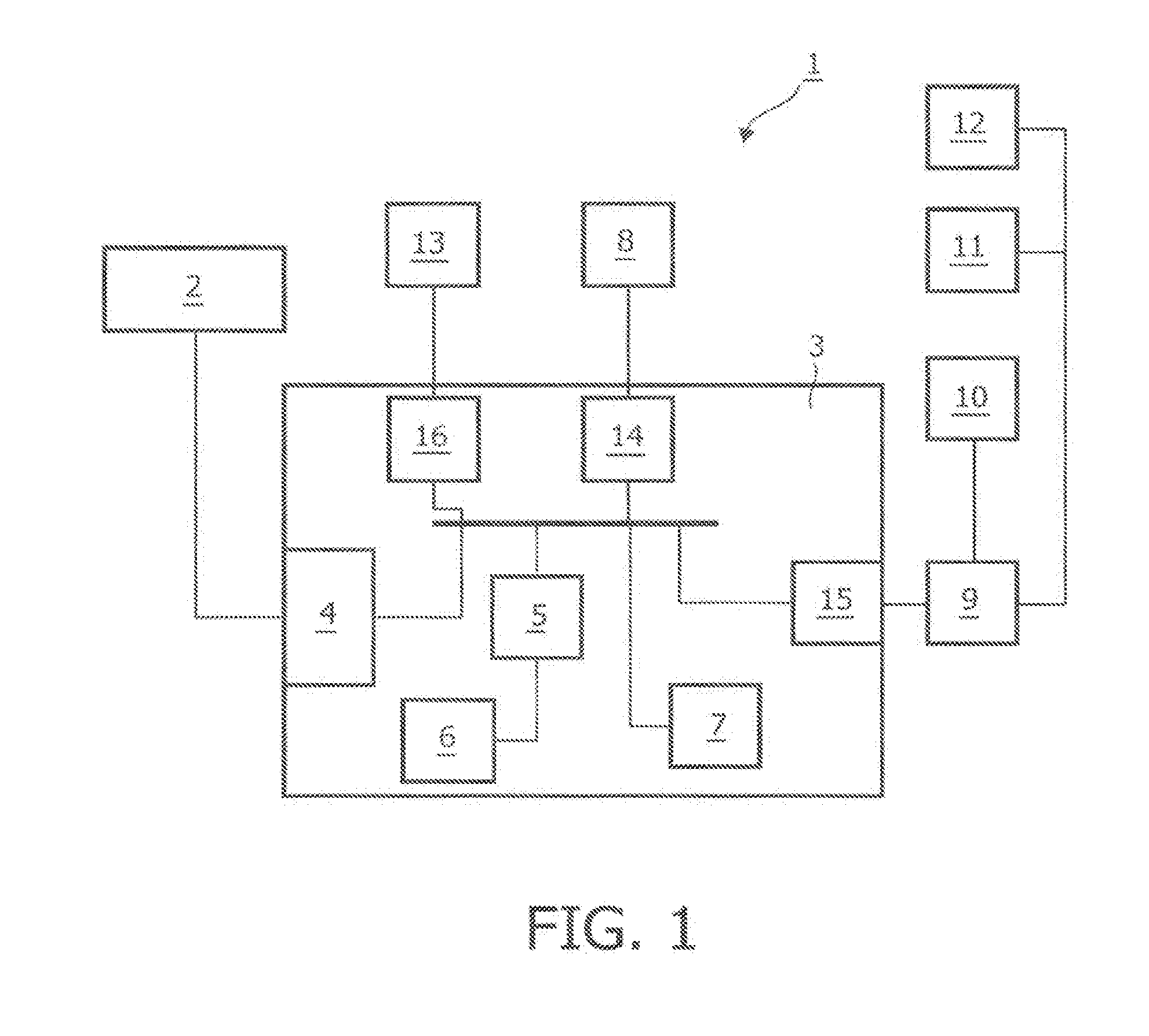
[0053]Referring to FIG. 1, an example is given here of a system 1 that is arranged to process a sequence of images. The system 1 carries out this processing in order to determine at least one of the presence and a frequency value of at least one peak in a spectrum of a signal based on the pixel data of the images corresponding to a frequency of a periodic physiological phenomenon. In certain embodiments, the presence of a living being is inferred from the presence of the peak, and used as a binary input for one or more system processes. The frequency of the peak is used as an input in at least one of those processes. In other embodiments, the presence of several different living beings is inferred. In one embodiment, this information is used as an input to an image segmentation method. In another embodiment, this information is used to provide spatially targeted feedback.

[0054]The system 1 includes a digital camera 2 arranged to record a sequence of digital images in quick successio...


PUM


Abstract

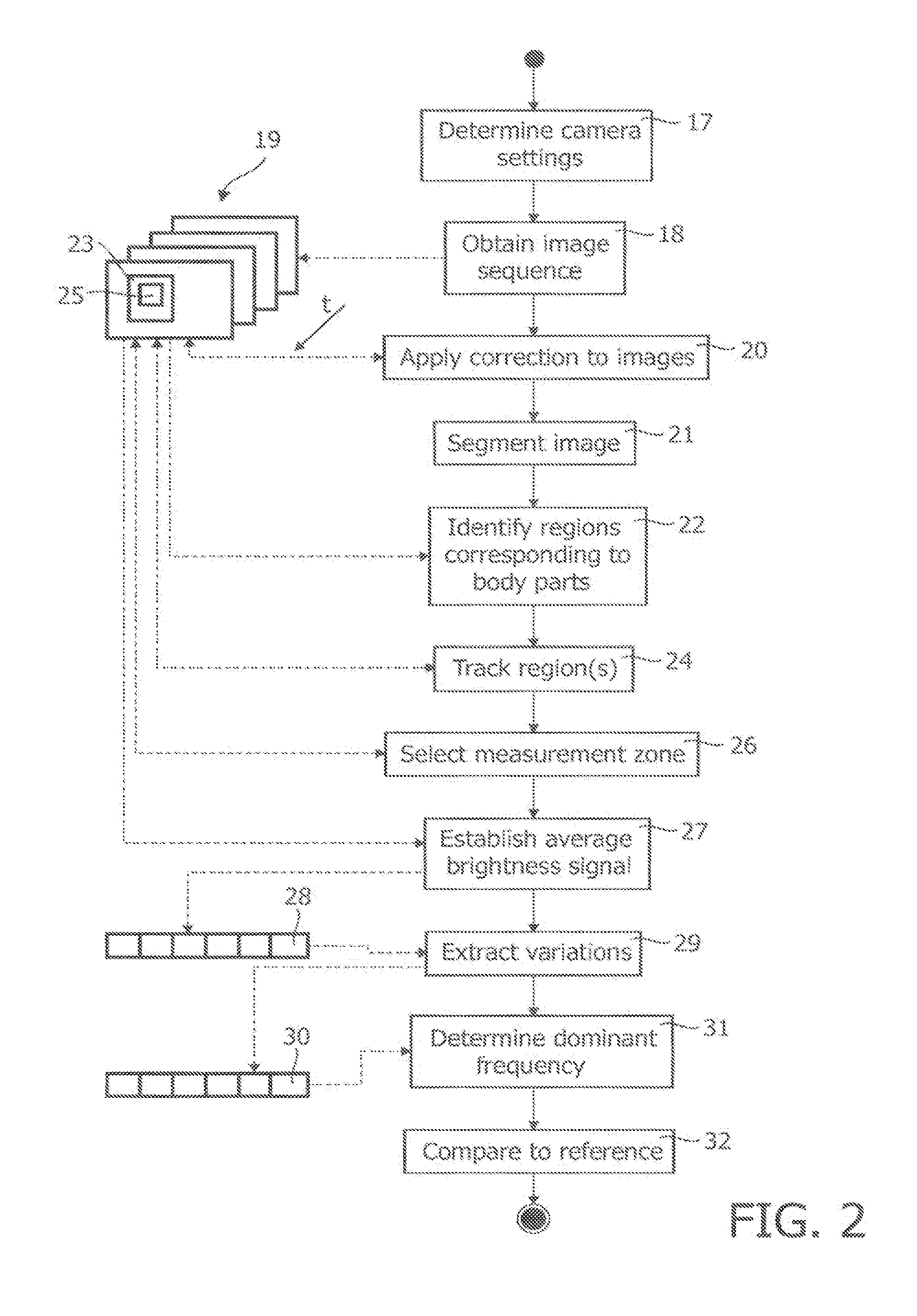
A method of controlling a function of a device, includes obtaining a sequence (19;34;48) of digital images taken at consecutive points in time. At least one measurement zone (25) including a plurality of image points is selected. For at least one measurement zone (25), a signal (30;41;55) representative of at least variations in a time-varying value of a combination of pixel values at at least a number of the image points is obtained and at least one characteristic of the signal (30;41;55) within at least a range of interest of its spectrum relative to comparison data is determined. The determination comprises at least one of:(i) determining whether the signal (30;41;55) has a spectrum with a local maximum at a frequency matching a comparison frequency to a certain accuracy; and(ii) determining whether at least a certain frequency component of the signal (30;41;55) is in phase with a comparison signal to a certain accuracy. The function is controlled in dependence on whether the determination is positive.

Description

CROSS-REFERENCE TO PRIOR APPLICATIONS[0001]This application is a continuation of co-pending U.S. patent application Ser. No. 13 / 254,863, filed Sep. 6, 2011, which is a U.S. National Stage Application under 35 U.S.C. §371 of International Application No. PCT / IB2010 / 050869, filed on Mar. 1, 2010, which claims the benefit of European Patent Application No. 09154491.6, filed Mar. 6, 2009. These prior applications hereby are incorporated herein by reference.FIELD OF THE INVENTION[0002]The invention relates to a method of controlling a function of a device.[0003]The invention also relates to a system for detecting the presence of a living being.[0004]The invention also relates to a computer program.BACKGROUND OF THE INVENTION[0005]Verkruysse et al., “Remote plethysmographic imaging using ambient light”, Optics Express, 16 (26), 22 Dec. 2008, pp. 21434-21445 demonstrates that photoplethysmography signals can be measure remotely on the human face with normal ambient light as the source and ...

Claims


Application Information

Patent Timeline
Patent Type & Authority Applications(United States)
IPC IPC(8): G06K9/00
CPCG06K9/00362G06T2207/20021G06T2207/30076G06T2207/30196G06T2207/30242G06T7/215G06V40/166G06V40/10
Inventor CENNINI, GIOVANNIJEANNE, VINCENT
Owner KONINKLJIJKE PHILIPS NV
Learn More