Motor vehicle with retractable steering wheel

a technology of steering wheel and motor vehicle, which is applied in the direction of steering parts, mechanical steering, vehicle components, etc., to achieve the effect of preventing the steering column from yielding and improving the integration of the driver

Inactive Publication Date: 2014-01-30
AUDI AG
View PDF4 Cites 73 Cited by
  • Summary
  • Abstract
  • Description
  • Claims
  • Application Information

AI Technical Summary

Benefits of technology

[0018]According to another advantageous feature of the present invention, a locking device can be provided in a region of the steering column to secure the steering column in an end position, in particular the position of manual steering. As a result, the airbag has a solid abutment in the crash position of the steering wheel. It may also be advantageous to lock the steering column so as to prevent the steering column to yield when the driver

Problems solved by technology

A retraction of the steering wheel makes it however necessary to alter an airbag system on the driver side, similar to the airbag system on the passenger s

Method used


Image

  • Motor vehicle with retractable steering wheel
  • Motor vehicle with retractable steering wheel
  • Motor vehicle with retractable steering wheel

Examples


first embodiment

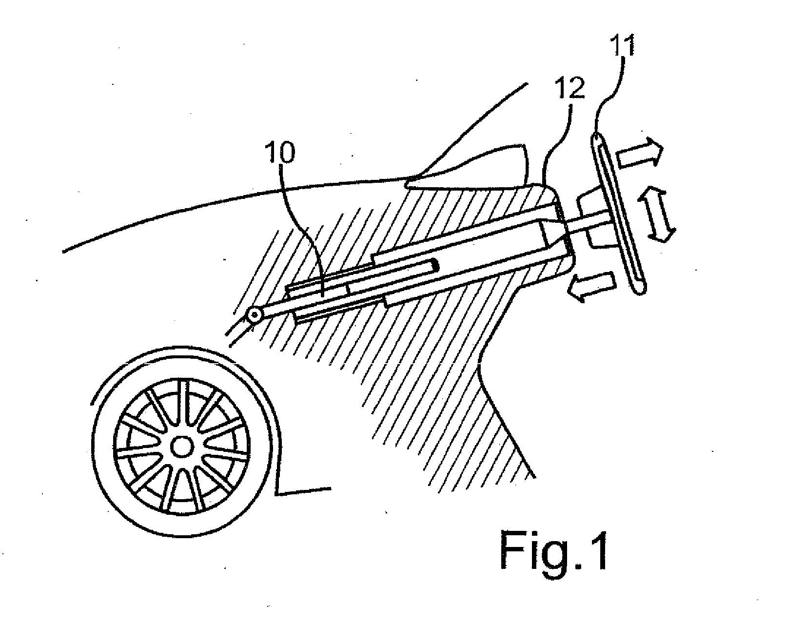
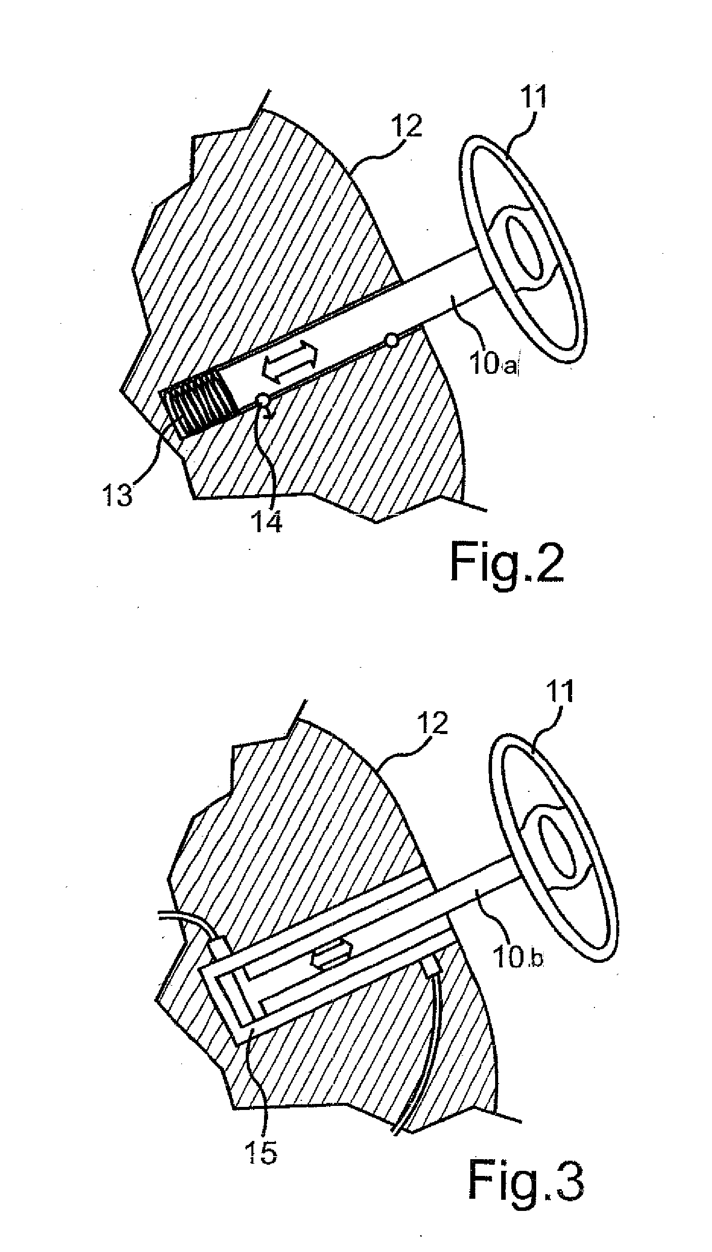
[0037]FIG. 2 shows a side view of a steering column, designated by reference numeral 10a. Parts corresponding with those in FIG. 1 are denoted by identical reference numerals and not explained again. In this embodiment, provision is made for an actuator which is essentially configured as a spring element 13 that is maintained under tension when the steering wheel 11 assumes the second position. A kinetic energy contained in the spring element 13 is sufficient to propel the steering wheel 11 in few milliseconds to the desired position. As the steering wheel 11 is shifted to the second position, the spring element 13 is tensioned. As depicted in FIG. 2 by way of example, the steering column 10 compresses hereby the spring element 13 which is locked in this position by a locking device 14 and thereby maintained under tension. Release of the spring element 13 is advantageously realized electromagnetically via a control device 19 (FIG. 5) which may also be used for deployment of the airb...

second embodiment

[0039]FIG. 3 shows a side view of a steering column 10b in which the actuator is configured in the form of a control element, advantageously as pneumatic or hydraulic cylinder 15. The pneumatic or hydraulic cylinder 15 has typically a gas or hydraulic reservoir for storing a gas or hydraulic fluid. In the event of an accident, the pneumatic or hydraulic cylinder 15 causes the attached steering column 10 to extend out of the dashboard 12, with the steering column 10 advantageously be constructed as piston of the pneumatic or hydraulic cylinder 15. Of course, the steering column 10b may also be moved by a separate piston of the pneumatic or hydraulic cylinder 15. A pressure force of the pneumatic or hydraulic cylinder 15 is dimensioned to enable propulsion of the steering wheel 11 from the second position to the first position within the required time. The need for a separate locking device can be dispensed with as a result of the pressure prevailing in the cylinder 15

third embodiment

[0040]FIG. 4 shows a side view of a steering column 10c in which the actuator is configured as an electric motor arranged in the region of the steering column 10c. The electric motor has a shaft which is connected to a pinion 16 in mesh with a toothed rack 17 which is arranged on the steering column 10c. In the event of an accident, the electric motor is activated to enable the steering column 10c to move to the first position as a result of a rotation of the pinion 16. In this position, the steering column 10c can be locked in place by locking the electric motor.

[0041]The electric motor can constructed as a linear motor arranged along the steering column 10c. The linear motor is activated in the event of an accident so that the extendible member of the steering column 10c can be moved in relation to a fixed member of the steering column 10c. Also in this variation, there is no need for the presence of a separate locking device to lock the steering column 10 in place when the desire...


PUM


Abstract

A motor vehicle includes an instrument panel, a steering column defining a longitudinal axis, and a steering wheel arranged on the steering column in a region of the instrument panel. The steering wheel is configured for movement in relation to the instrument panel in a direction of the longitudinal axis towards the instrument panel from a first position to a second position. The steering column is also constructed to enable the steering wheel to move from the second position to the first position when the motor vehicle is subjected to a force caused by an accident.

Description

CROSS-REFERENCES TO RELATED APPLICATIONS[0001]This application claims the priority of German Patent Application, Serial No. 10 2012 014 762.7, filed Jul. 25, 2012, pursuant to 35 U.S.C. 119(a)-(d), the content of which is incorporated herein by reference in its entirety as if fully set forth herein.BACKGROUND OF THE INVENTION[0002]The present invention relates in general to the field of motor vehicles.[0003]The following discussion of related art is provided to assist the reader in understanding the advantages of the invention, and is not to be construed as an admission that this related art is prior art to this invention.[0004]Motor vehicles are increasingly equipped with “steer-by-wire” steering systems, involving a mechanical or hydraulic decoupling of steering wheel or steering column and wheels of the vehicle. “Steer-by-wire” technology not only decreases weight by doing away with many mechanical components of the steering device but also provides for a so-called autopilot. The...

Claims


Application Information

Patent Timeline
IPC IPC(8): B62D1/19
CPCB62D1/192B62D1/197B62D5/001
Inventor STADLER, MICHAELSCHUTZ, INGO
Owner AUDI AG
Why Eureka
Try Eureka