Polarizing photovoltaic devices and applications in LCD displays and tandem solar cells

Inactive Publication Date: 2014-01-30
RGT UNIV OF CALIFORNIA
View PDF6 Cites 12 Cited by
  • Summary
  • Abstract
  • Description
  • Claims
  • Application Information

AI Technical Summary

Benefits of technology

[0011]A liquid crystal display according to an embodiment of the current invention includes a first polarizer; a second polarizer spaced apart from the first polarizer; and an electrically controllable liquid crystal element arranged between the first and the second polarizers. The first and sec

Problems solved by technology

From the energy point of view, LCD technology is very inefficient.
That is a great waste of energy, especially whe

Method used


Image

  • Polarizing photovoltaic devices and applications in LCD displays and tandem solar cells
  • Polarizing photovoltaic devices and applications in LCD displays and tandem solar cells
  • Polarizing photovoltaic devices and applications in LCD displays and tandem solar cells

Examples


example 1

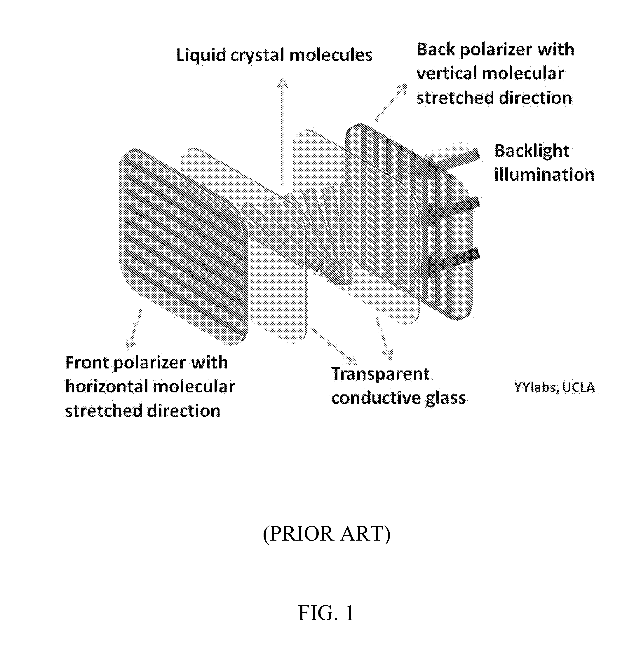
[0036]To solve the problem of energy waste in conventional LCDs, as mentioned in the Background, we present here the use of polarizing photovoltaic cells for recycling energy from the backlight. Traditional polarizing filters in LCD systems can be replaced by the polarizing photovoltaic cells, as is illustrated schematically in FIG. 5. The polarizing photovoltaic cells not only act as polarizing films to provide linearly polarized light, but instead of simply blocking the light, they absorb it and convert it into usable power which can be fed back into the system, hence increasing the overall efficiency of the system as a whole. FIG. 5 shows an example of LCD system according to an embodiment of the current invention that includes polarizing photovoltaic cells. When the isotropic light reaches the first polarizing photovoltaic film, the light portion with axis parallel to the molecular orientation of the first polarizing photovoltaic film will be absorbed. This portion of light ener...

example 2

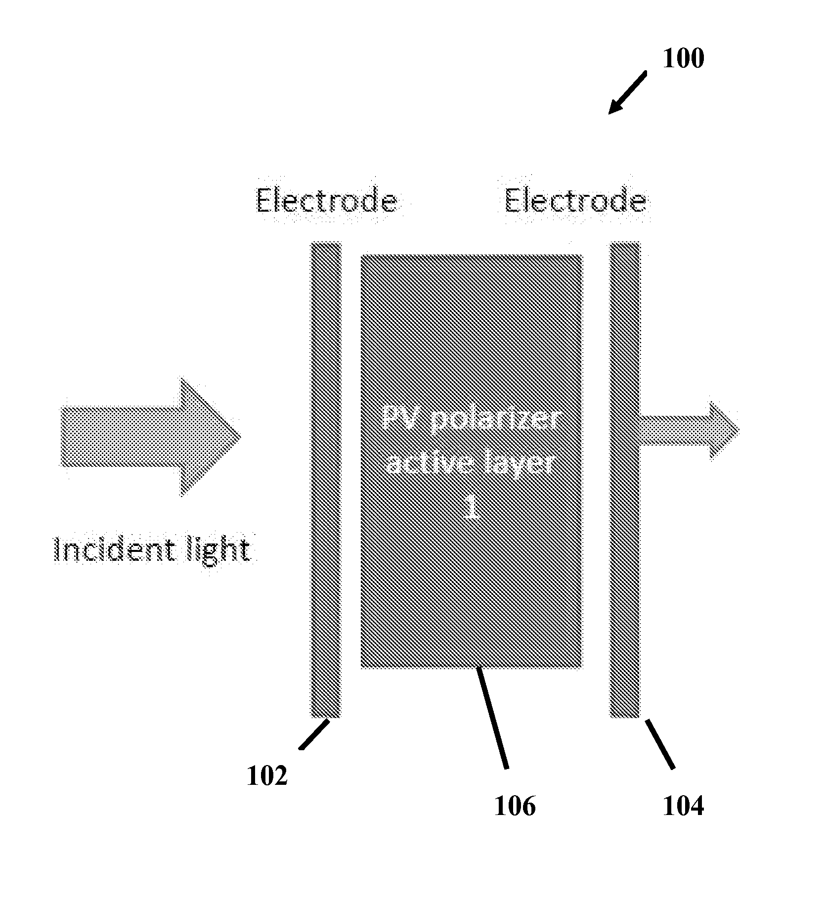
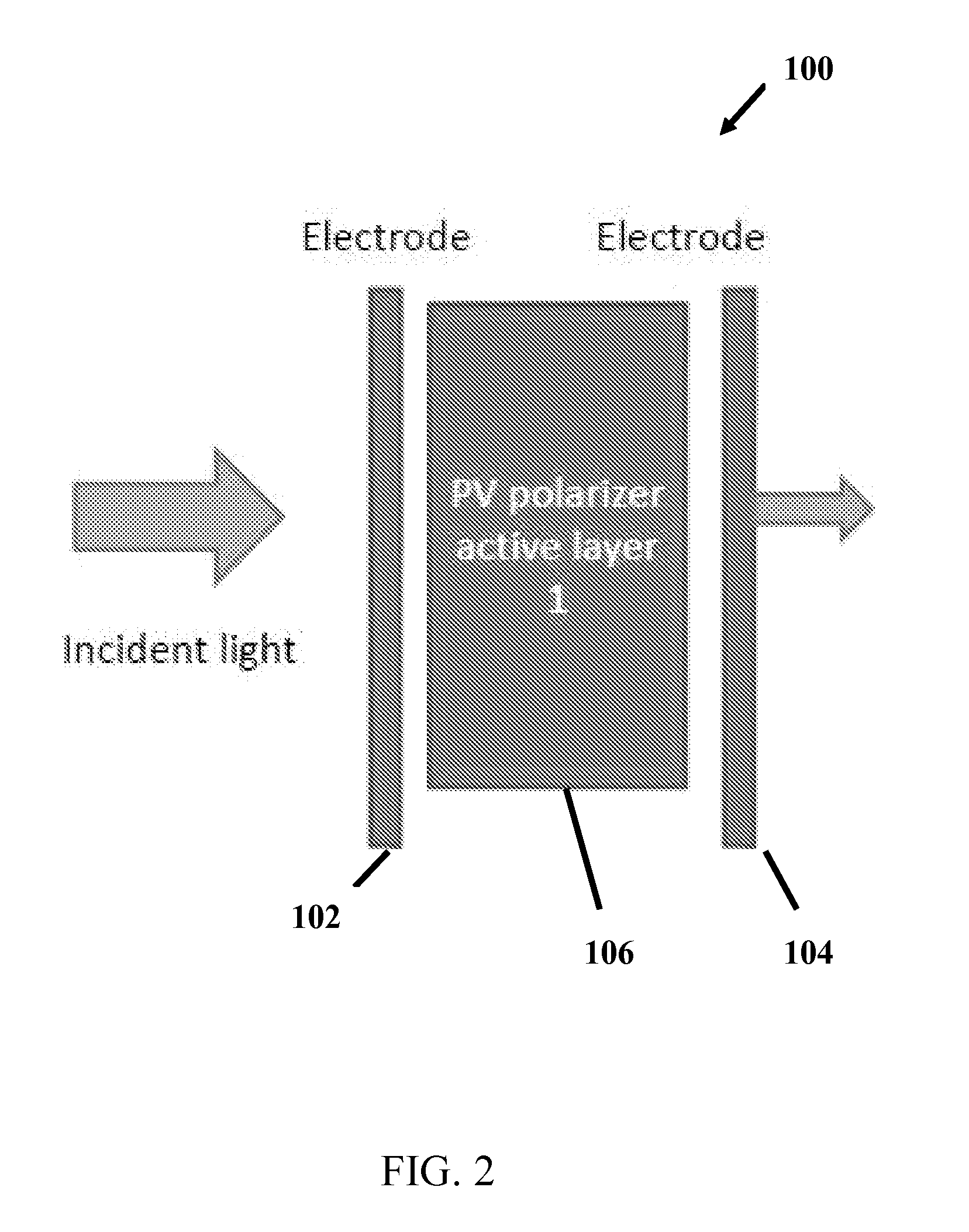
[0070]The polarizing organic photovoltaic device will be referred to as ZOPV instead of POPV (polymer organic photovoltaic). Compared with their silicon or other inorganic or organic-inorganic hybrid counterparts, a unique advantage of organic conjugated materials is that the molecular chains can be easily oriented, leading to anisotropic response to polarized incident light. This feature can make the organic PV system superior to the inorganic PV system for PV polarizer purposes. ZOPV devices integrated into an LCD panel (FIGS. 10A, 10B) can have three potential benefits: 1) polarization, whereby the EM wave component with an electric field perpendicular to the oriented molecular chain (s-mode polarized light) propagates through the film without absorption, serving its conventional role in LCDs; 2) As a PV device, the ZOPV film harvests the EM wave component parallel to the molecular chain orientation (p-mode polarized light, which is absorbed and wasted in a conventional LCD), con...


PUM

PropertyMeasurementUnit
Ratioaaaaaaaaaa
Transparencyaaaaaaaaaa
Wavelengthaaaaaaaaaa

Abstract

An electro-optic device includes a first electrode, a second electrode spaced apart from the first electrode, and an active layer of organic semiconducting material between the first electrode and the second electrode. The active layer includes a quasi-bilayer in which a first plurality molecules from a first layer of active material is interpenetrated by a second plurality of molecules from a second layer of active material formed on the first layer. The first and second pluralities of molecules provide donor-acceptor pairs such that the quasi-bilayer has at least a portion that is a bulk heterojunction active layer. Each of the first plurality of molecules has a long axis that is longer than corresponding transverse axes and the long axis is substantially aligned along a common direction such that the active layer is more sensitive to a first polarization of incident light than a second polarization of the incident light, wherein the first polarization and the second polarization are orthogonal polarization components of the light.

Description

CROSS-REFERENCE OF RELATED APPLICATION[0001]This application claims priority to U.S. Provisional Application No. 61 / 474,074 filed Apr. 11, 2011, the entire contents of which are hereby incorporated by reference.[0002]This invention was made with U.S. Government support of Grant No. N00014-04-1-0434, awarded by the Office of Naval Research, DOD. The U.S. Government has certain rights in this invention.BACKGROUND[0003]1. Field of Invention[0004]The field of the currently claimed embodiments of this invention relates to electro-optic devices, and more particularly to polarizing photovoltaic components and devices that incorporate the components.[0005]2. Discussion of Related Art[0006]Liquid crystal display (LCD) technology is currently the most popular information display technology. Its uses include monitors for computers, laptops, televisions, instrument panels, projectors, and other electronic devices ranging from aircraft cockpit displays to every-day consumer electronic devices.[0...

Claims


Application Information

Patent Timeline
IPC IPC(8): G02F1/1335H01L31/18H01L51/42
CPCG02F1/133528H01L31/18H01L51/42G02B5/3025Y02E10/549B82Y10/00G02F1/13324H10K30/57H10K71/191H10K85/113H10K85/215H10K30/30H10K30/00
Inventor YANG, YANGZHU, RUI
Owner RGT UNIV OF CALIFORNIA
Why Eureka
Try Eureka