Light source for an automotive headlight with adaptive function

Active Publication Date: 2014-01-30
SHARP KK
View PDF13 Cites 169 Cited by
  • Summary
  • Abstract
  • Description
  • Claims
  • Application Information

AI Technical Summary

Benefits of technology

[0017]For the avoidance of doubt, the term “ph

Problems solved by technology

By necessity, the dipped beam also creates a restricted view of the road due to restricted illumination of the same.
The removal of light is performed by a shield, which is inserted into the light path thereby causing a reduction in optical efficiency of the projector headlight.
The filament and discharge light sources provide no means for modification of the output from the source.
The provision of only a dipped beam distribution, or of only a driving beam distribution, has limitations in terms of road user safety by not providing simultaneous optimal

Method used


Image

  • Light source for an automotive headlight with adaptive function
  • Light source for an automotive headlight with adaptive function
  • Light source for an automotive headlight with adaptive function

Examples


Embodiment Construction

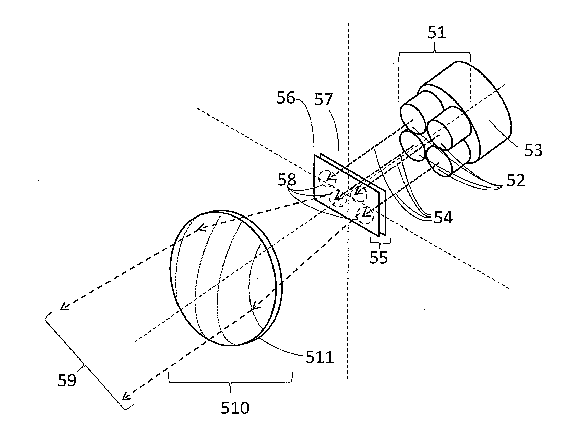
[0131]The main embodiment of the present invention is described herein. An overview of the method of operation is presented in FIG. 5a. A group of laser light sources 51 is comprised of an array of multiple individual laser emitters 52. The laser emitters 52 may be mounted on a heat sink 53 if necessary. From herein the heat sink 53 will be omitted from figures for clarity, but may always be associated with laser emitters 52 or a laser emitter array 51. The laser emitters 52 emit light beams 54 of a first waveband. The light beams 54 of the first waveband from the laser emitters 52 are directed onto a light source 55 comprising a photoluminescent material 56 which is deposited onto a substrate 57. The following description will assume that the number of light-emitting devices is equal to the number of light beams, ie that each light-emitting device generates, when ON, a single beam light incident on the photoluminescent material. The invention is not however limited to this. From he...


PUM


Abstract

A light source system operable in at least first and second modes to provide at least and first and second different far field illumination patterns, the system comprising: a photoluminescent material; and a light beam generator for generating, in the first mode, a first set of light beams for illuminating respective first regions of the photoluminescent material and for generating, in the second mode, a second set of light beams for illuminating respective second regions of the photoluminescent material, the first and second sets of light beams being independently controllable. In the first mode, the light beam generator generates the first set of light beams such that a first beam of the first set of light beams illuminates a first illumination region of the photoluminescent material having one side that is inclined with respect to another side of the illumination region.

Description

[0001]This Nonprovisional application claims priority under 35 U.S.C. §119(a) on Patent Applications No. 1213301.3 filed in United Kingdom on Jul. 26, 2012, the entire contents of which are hereby incorporated by reference.TECHNICAL FIELD[0002]The present invention relates to a light source for a non-mechanically switchable headlight system for the provision of an illumination pattern on the road which may be adapted to best suit driving conditions.BACKGROUND ART[0003]The application of lighting to the automotive industry is well known. The original electric light sources were filament bulbs which offered high luminance from a small source. Improvements in light source design led to halogen type filament bulbs, high intensity discharge (HID) bulbs or high brightness light emitting diodes (LED). These offer improvement in terms of luminance and energy use over preceding filament bulbs. In order to apply these light sources to automotive front lighting and realise the beam spot distri...

Claims


Application Information

Patent Timeline
IPC IPC(8): F21V9/16F21S8/10B60Q1/04F21V13/14
CPCF21V9/16B60Q1/04F21S48/1225F21V13/14B60Q1/143B60Q2300/21B60Q2300/42B60Q2300/45F21S41/16F21S41/176F21S41/663F21V9/30B60Q1/076F21K2/00F21S41/14
Inventor SUCKLING, JAMES ROWLANDMONTGOMERY, DAVID JAMESMITCHELL, SARAH ANNETAKAHASHI, KOJI
Owner SHARP KK
Why Eureka
Try Eureka