Torque transmission device

a transmission device and torque technology, applied in the direction of road vehicle drive control system, vehicle design optimisation, vehicle sub-unit features, etc., can solve the problem of not increasing the installation space provided for them to the same degree, and achieve the effect of increasing operational reliability

Active Publication Date: 2014-02-06
SCHAEFFLER TECH AG & CO KG
View PDF2 Cites 8 Cited by
  • Summary
  • Abstract
  • Description
  • Claims
  • Application Information

AI Technical Summary

Benefits of technology

[0006]It is an object of the present invention to provide a torque transmission device, in particular for a drive train of

Problems solved by technology

In conventional motor vehicles, during non-negligible periods of time, the drive motor, frequently a combustion engine including a reciprocating piston, is operated in unfavorable ranges of operation; moreover, in particular during braking operations, energy that has previously b

Method used


Image

  • Torque transmission device
  • Torque transmission device
  • Torque transmission device

Examples


Embodiment Construction

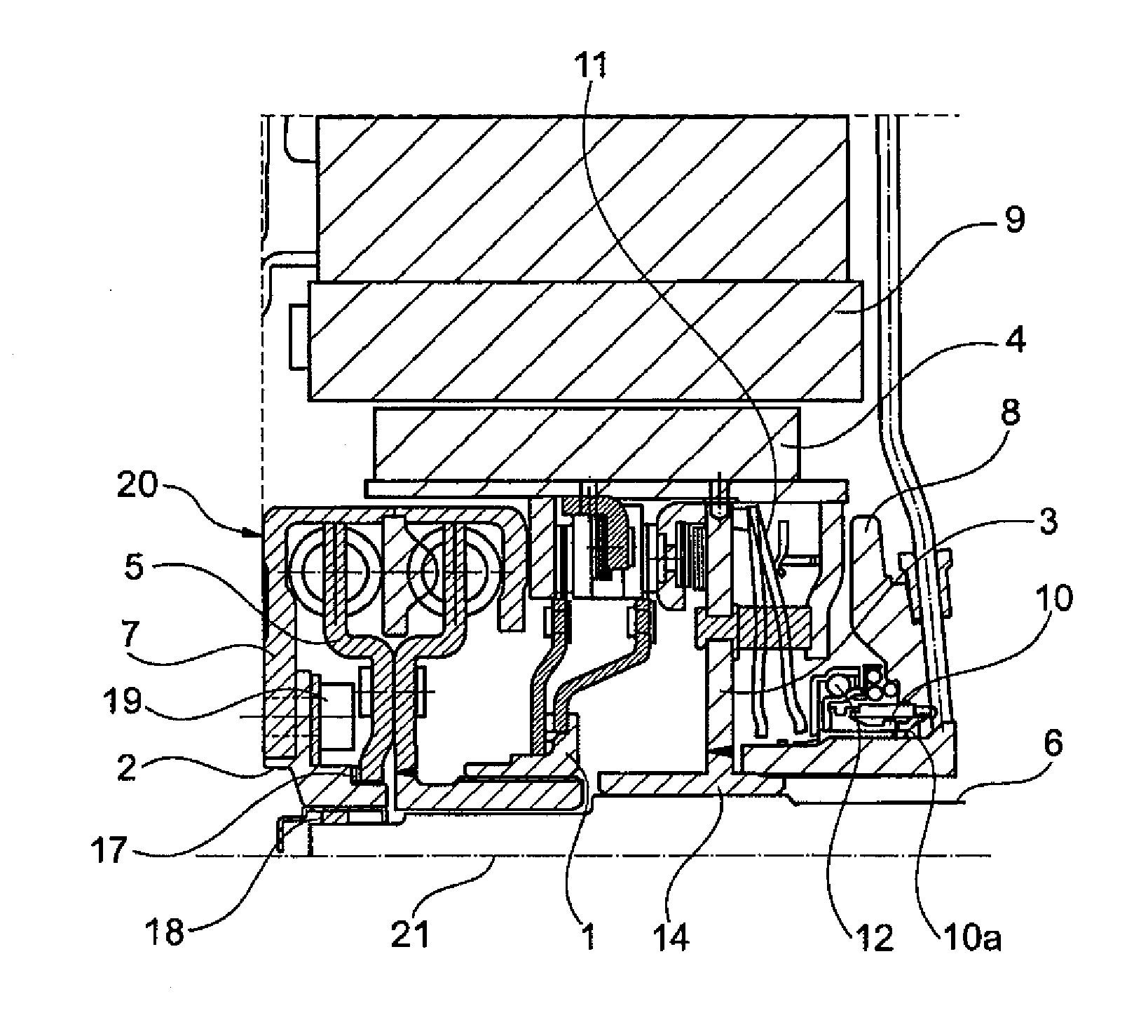
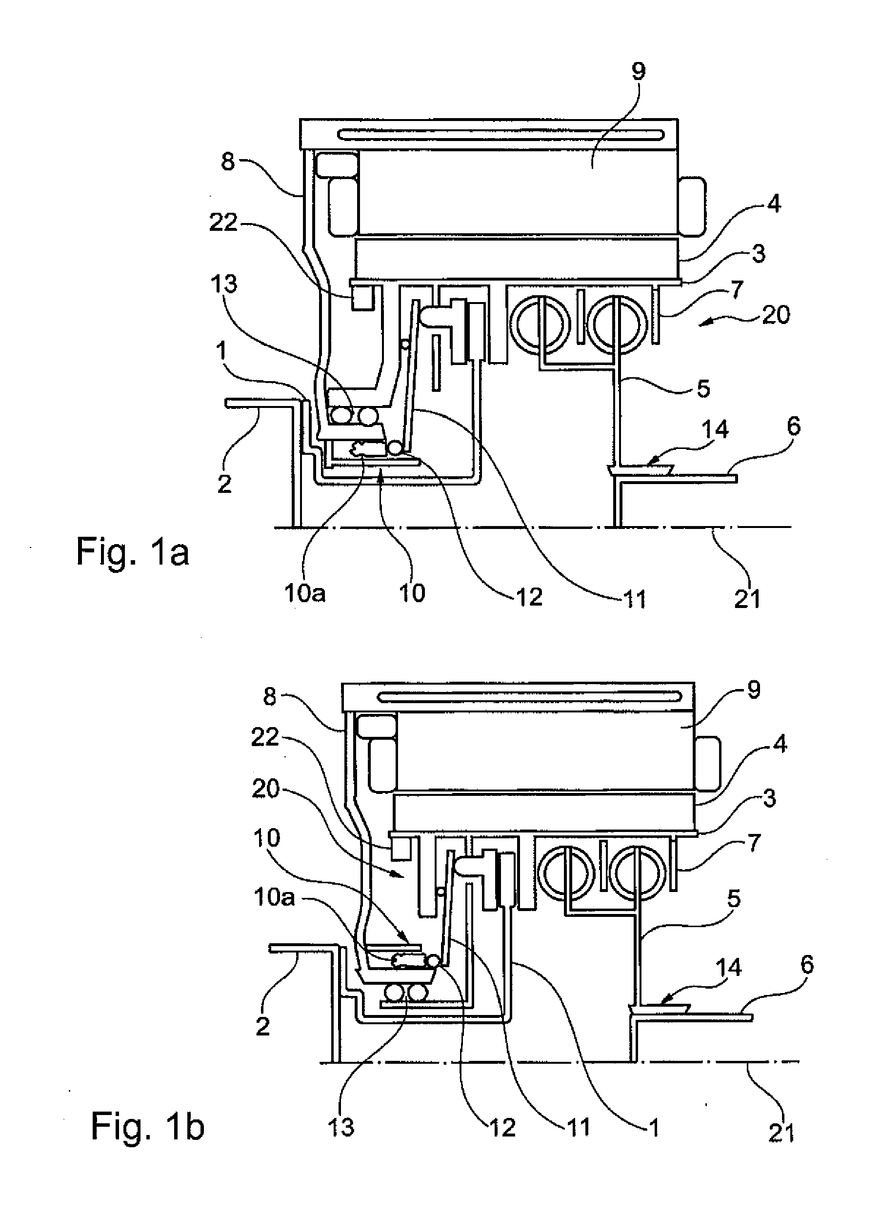
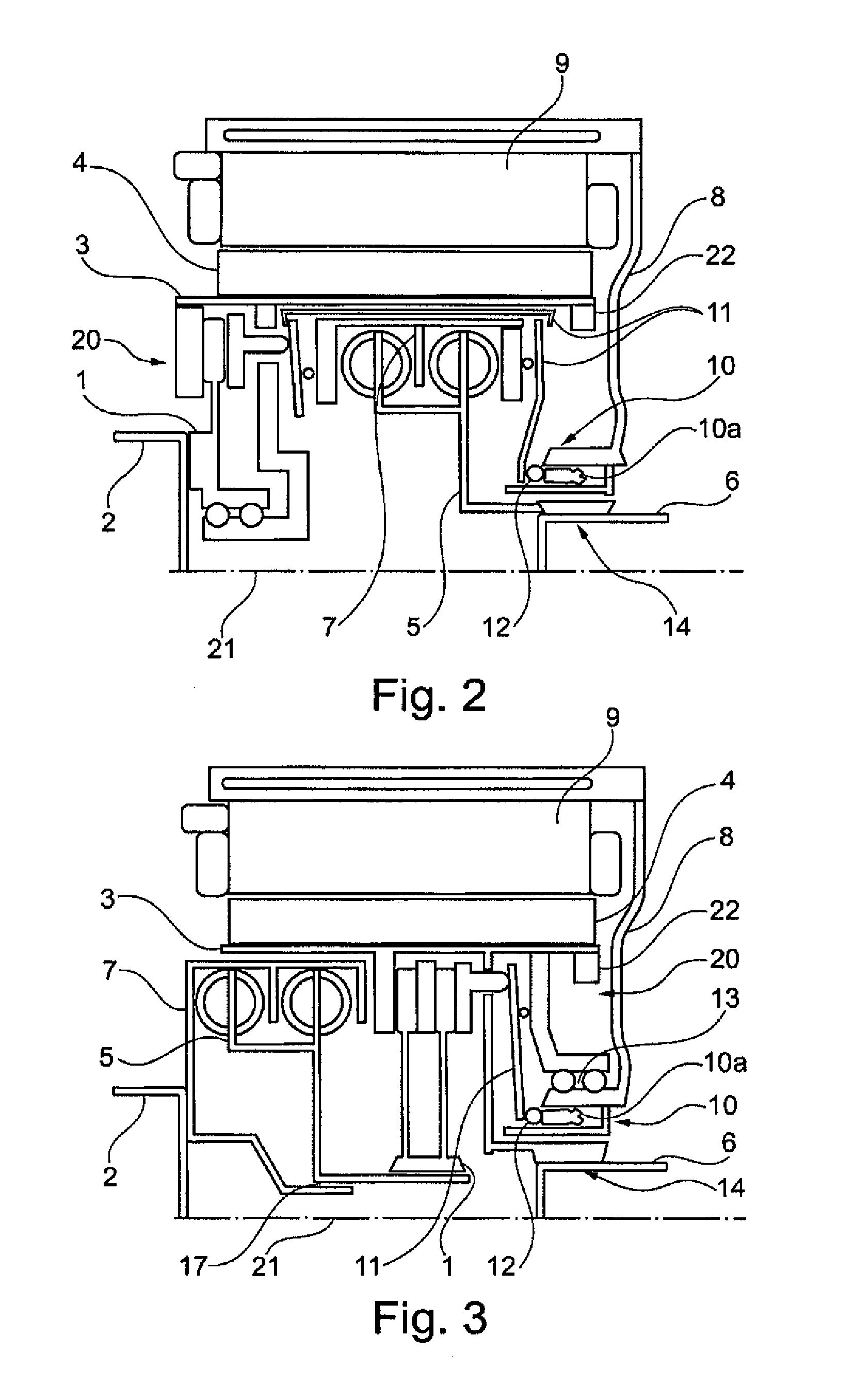
[0113]FIGS. 1a and 1b illustrate different exemplary embodiments of a torque transmission device. In the embodiments shown in FIGS. 1a and 1b, the transmission input element 1 is coupled to the primary power take-off shaft 2, the transmission output element 3 is coupled to the rotor device 4, and the damper output element 5 is coupled to the drive train shaft 6. In addition, the damper input element 7 and the transmission output element 3 are coupled to each other. The torque transmission device is essentially arranged inside a rotor recess 20, and the rotor device 4 is supported for rotation about its axis of rotation 21.

[0114]The transmission output element 3 is supported for rotation in a housing portion 8 that is stationary relative to said rotor device 4. In the region of the stationary housing portion 8, a sensor device 22 is provided to record the rotary speed of the rotor device. Said rotor device 4 is supported for rotation in a stator device 9. The transmission actuation d...


PUM


Abstract

A torque transmission device for the drive train of a passenger car. The drive train includes two engines, wherein one of said engines is an electromechanical energy converter. The torque transmission device is inserted into a rotor recess, which is arranged in a rotor assembly of the electromechanical energy converter.

Description

[0001]This is a continuation and claims the benefit of International Application PCT / DE2012 / 000398, filed Nov. 5, 2013 which claims the benefit of German Patent Application DE 10 2011 100 694.3, filed May 5, 2011, both applications being hereby incorporated by reference herein.[0002]The present invention relates to device for transmitting torque, in particular in a drive train of a motor vehicle. The invention will be described below in connection with a driving assembly for an automobile having multiple engines. It is to be understood that the proposed torque transmission device may be used independently of the construction of the motor vehicle and of the drive train.BACKGROUND[0003]Modern motor vehicles not only have to meet high expectations in terms of road performance (such as acceleration, maximum speed) and driving comfort (such as noise, vibration, and harshness behavior, NVH) but also in terms of the efficient use of resources available to the drive, in particular fuel cons...

Claims


Application Information

Patent Timeline
IPC IPC(8): F16D23/12
CPCF16D23/12B60K6/26B60K6/387B60K6/48B60Y2300/205B60Y2304/01B60Y2400/4242F16F15/121Y02T10/62
Inventor REITZ, DIERKRUDER, WILLIMACKOWIAK, STEFAN
Owner SCHAEFFLER TECH AG & CO KG
Why Eureka
Try Eureka