Sealed cell and method for manufacturing same

a technology of sealed cells and welded parts, applied in the direction of secondary cells servicing/maintenance, cell components, cell component details, etc., can solve the problems of difficult welding to each other, reducing production efficiency, and melting point and electrical characteristics, and achieve high melting point, high productivity, and high melting point

Inactive Publication Date: 2014-02-06
SANYO ELECTRIC CO LTD
View PDF4 Cites 15 Cited by
  • Summary
  • Abstract
  • Description
  • Claims
  • Application Information

AI Technical Summary

Benefits of technology

[0020]With the above-described advantageous effects, a sealed cell having a highly conductive and space saving sealing body with a safety valve can be manufactured at high productivity.
[0021]After the step of temporary fixation, the bent portion may be pressed from outside to reinforce the temporarily fixed portion.
[0022]The conductive adhesion can be achieved by welding or using a conductive adhesive agent. Examples of the welding include high-energy beam welding with a laser beam or electron beam, ultrasonic welding, and soldering. The most preferable of these welding techniques is laser welding. The conductive adhesive agent can be of a well-known type such as a conductive filler dispersed in a binder. It is preferable that the binder be an epoxy-based resin, and that the conductive filler be a metal powder such as silver powder, nickel powder, gold plated powder, or palladium powder, or carbon powder.
[0023]In the case of laser welding, a laser beam can be applied mainly to either the flange or the peripheral portion depending on which is made of a material having a higher melting point. This allows proper welding while suppressing evaporation.
[0024]The safety valve is generally made of a deformable aluminum-based material (pure aluminum or an aluminum alloy), whereas the terminal cap is generally made of an iron-based material having a certain strength (iron or an iron alloy). In the case of welding them, it is preferable to apply a laser beam mainly to the terminal cap made of a material having a higher melting point.
[0025]When welding is applied to the entire boundary which is between the flange and the peripheral portion, and is near the bent portion (the outer periphery of the bent portion), no gap is formed therebetween. This eliminates the occurrence of liquid leakage through a gap, for example, at an increase in the cell internal pressure.

Problems solved by technology

These materials, however, greatly differ in melting point and electrical characteristics from each other, and are consequently difficult to be welded properly to each other (to reduce the resistance between them).
In the technique of Patent Document 1, however, preparing the sealing body involves forming and aligning the pin-shaped projections and the counterbored holes, and then rivet-fixing and welding them to each other, which decreases the production efficiency.
These techniques, however, require securing some of the components together by caulking or preparing additional components for welding.
This causes an increase in the volume of the sealing body and in the man-hours to produce it, thereby hindering productivity improvement and cell capacity increase.

Method used


Image

  • Sealed cell and method for manufacturing same
  • Sealed cell and method for manufacturing same
  • Sealed cell and method for manufacturing same

Examples


first embodiment

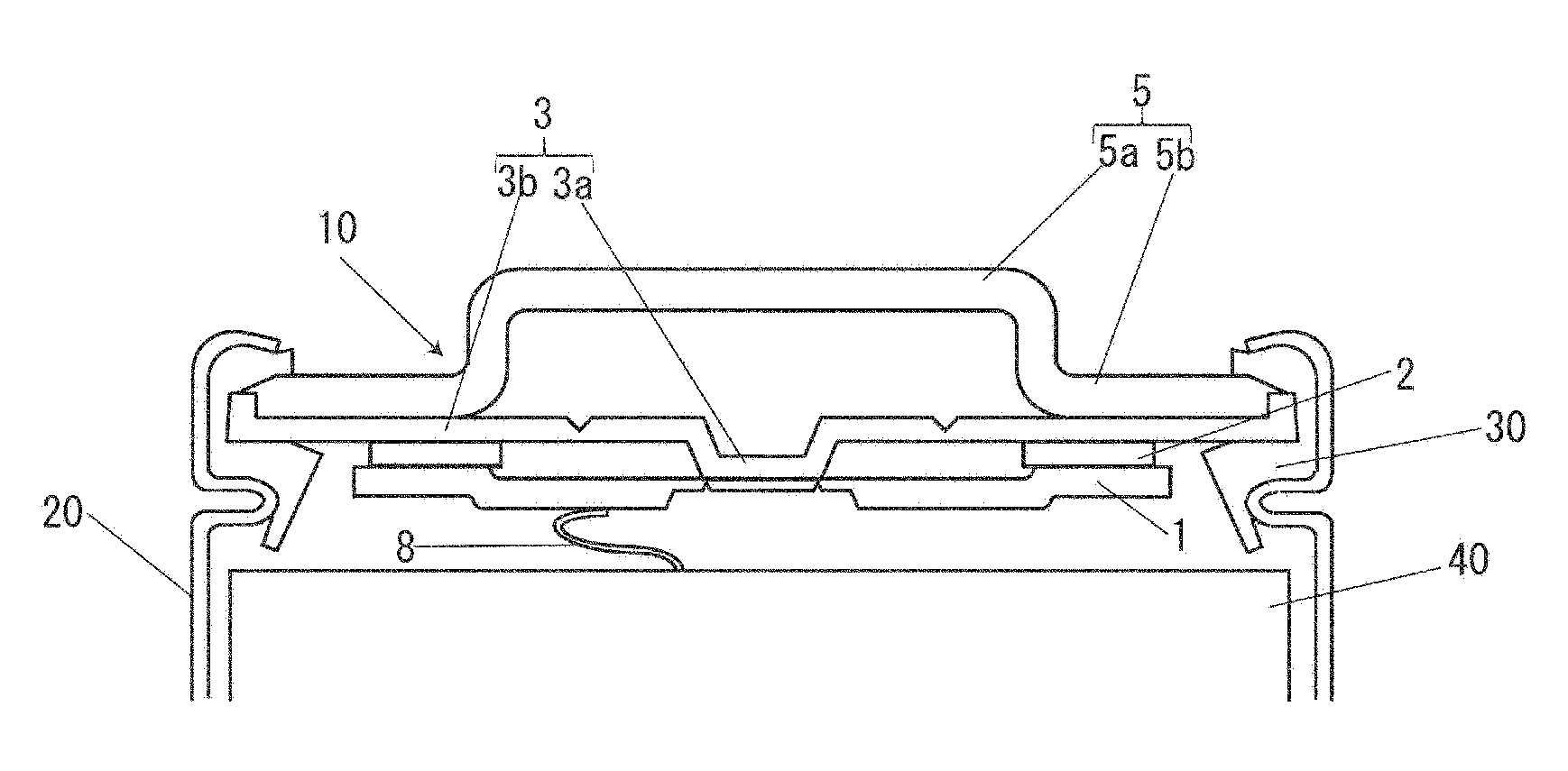
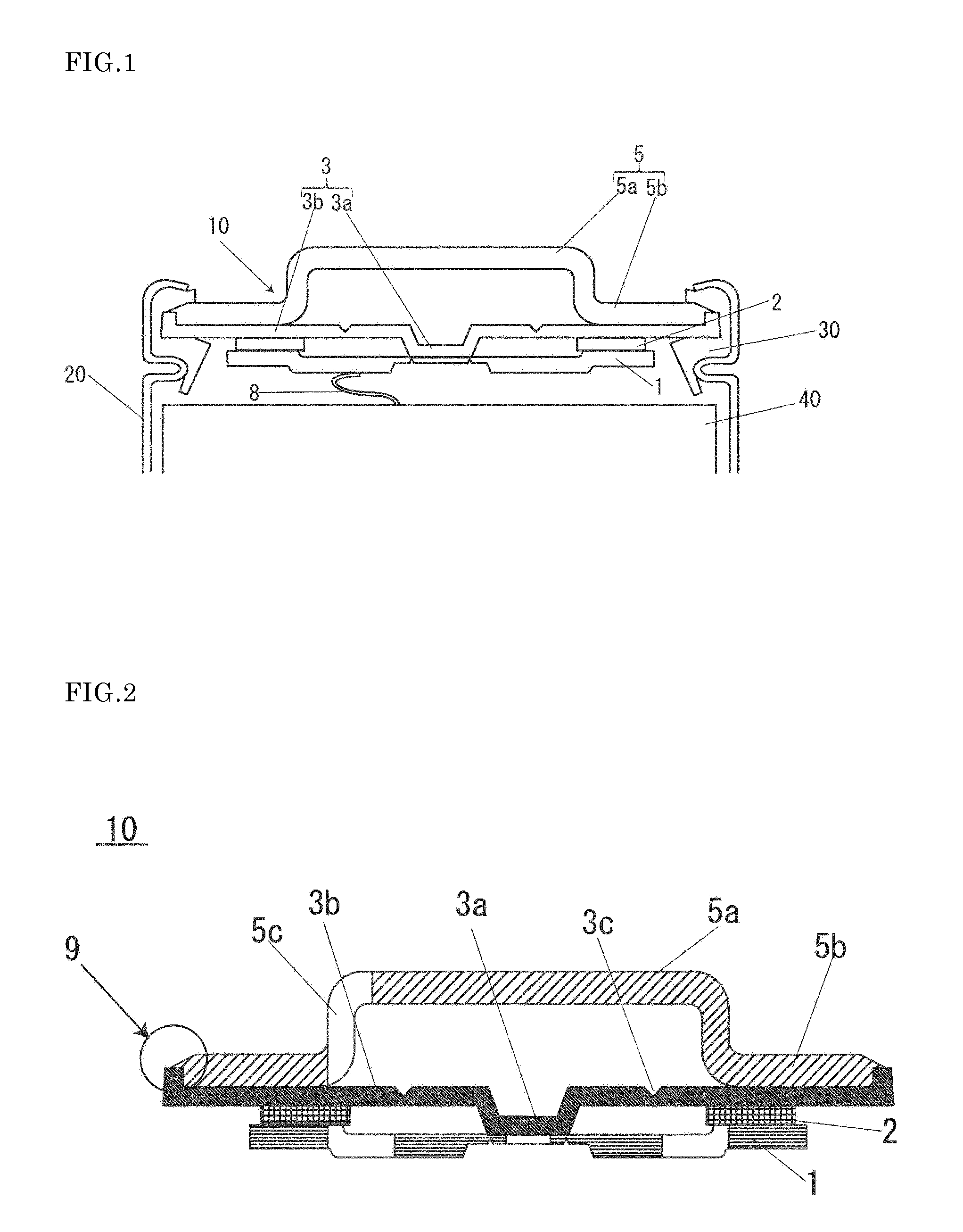
[0033]As an embodiment of the present invention, a lithium-ion secondary cell will now be described in detail as follows with reference to the drawings. FIG. 1 is a partially enlarged sectional view of a sealed cell of the present embodiment, and FIG. 2 shows a sealing body used for the sealed cell of the present invention.

[0034]As shown in FIG. 1, the sealed cell of the present embodiment includes an outer can 20 accommodating an electrode assembly 40 and a non-aqueous electrolyte, and a sealing body 10 secured by caulking to the opening of the outer can 20 with an insulation gasket 30 interposed therebetween.

[0035]As shown in FIGS. 1 and 2, the sealing body 10 used for the sealed cell of the present embodiment includes a terminal plate 1 electrically connected to either the positive or negative electrode via an electrode tab 8; a terminal cap 5 having an external terminal 5a projecting toward the outside of the cell; a safety valve 3 disposed between the terminal plate 1 and the t...

example 1

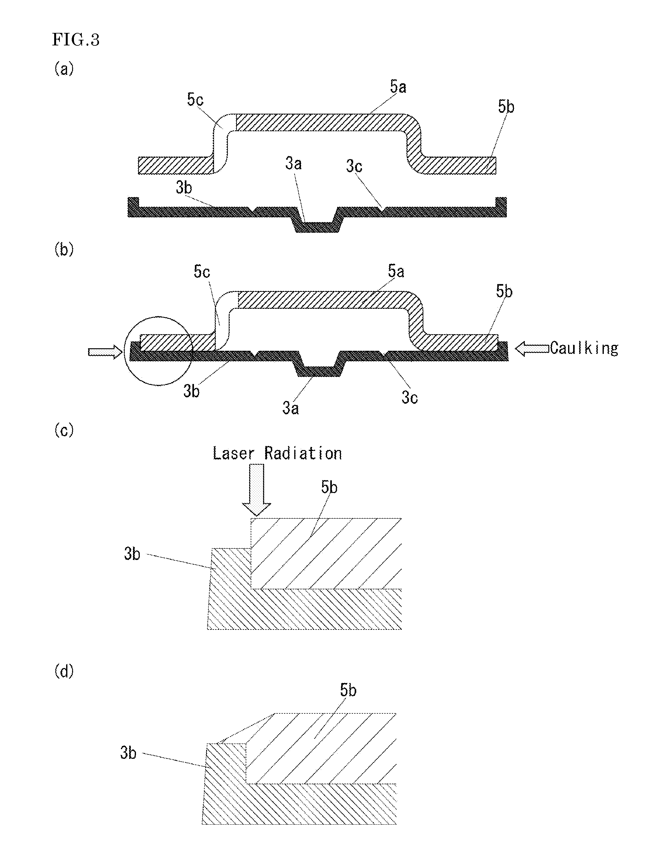
[0074]The reason for this result is assumed as follows. In Example 1, the safety valve and the terminal cap are welded to each other throughout the outer periphery, leaving no gap therebetween. In Comparative Example 1, on the other hand, the safety valve and the terminal cap are welded to each other only between the pin-shaped projections and the counterbored holes, leaving gap on the outer periphery.

[0075]Welding Reliability Test

[0076]The cells of Example 1 and the cells of Comparative Example 1 were charged at a constant current of 1 It (1250 mA) until the voltage reached 4.2 V, and then at a constant voltage of 4.2 V until the current reached 0.02 It (25 mA). After this, these cells were placed in a constant temperature chamber in which the temperature changed from −30° C. to 70° C. in 0.5 hours, and were subjected to 400 cycles when a temperature change from −30° C. to 70° C. and then back to −30° C. is defined as one cycle. The resistance between the safety valve and the termi...


PUM

PropertyMeasurementUnit
thicknessaaaaaaaaaa
diameteraaaaaaaaaa
heightaaaaaaaaaa

Abstract

An object of the present invention is to manufacture a sealed cell having a highly conductive sealing body with a safety valve at high productivity. In order to accomplish above object, the present invention espouses a method of manufacturing a sealed cell including: preparing a terminal cap and a safety valve, the terminal cap including an external terminal projecting toward the outside of the cell, and a flange, and the safety valve including a conductive contact portion projecting toward the inside of the cell, and a peripheral portion and having an outer periphery bent toward the outside of the cell so as to form a bent portion; temporarily fixing the safety valve and the terminal cap together at the bent portion after coupling the safety valve and the terminal cap to each other; and conductively adhering the flange and the peripheral portion to each other near the bent portion.

Description

TECHNICAL FIELD[0001]The present invention relates to a sealed cell, and more particularly, to a sealed cell having a sealing body with a safety valve.BACKGROUND ART[0002]Non-aqueous electrolyte secondary cells have been widely used as power sources of mobile devices, electric tools, etc. because of their high energy density and high capacity.[0003]Such a non-aqueous electrolyte secondary cell contains a flammable organic solvent, and is therefore required to ensure safety. For this reason, the sealing body for sealing the cell is equipped with a current breaking mechanism, which operates when the cell internal pressure increases (see, for example, Patent Document 1).[0004]The technique of Patent Document 1 will now be described with reference to FIG. 4. FIG. 4 is a partially enlarged sectional view showing the sealed cell of Patent Document 1. As shown in FIG. 4, the cell includes an outer can 20 accommodating an electrode assembly 40 and a non-aqueous electrolyte, and a sealing bo...

Claims


Application Information

Patent Timeline
Patent Type & Authority Applications(United States)
IPC IPC(8): H01M2/12H01M50/171
CPCH01M2/1235H01M50/56H01M50/171H01M50/152H01M50/3425Y10T29/4911Y02E60/10H01M50/342
Inventor YAMATO, KENJIYAMASHITA, SYUICHIYAMAGUCHI, YUMA
Owner SANYO ELECTRIC CO LTD
Why Eureka
Try Eureka