
Compact portable apparatus for optical assay

Active Publication Date: 2014-02-06
INGENERON
View PDF3 Cites 36 Cited by
  • Summary
  • Abstract
  • Description
  • Claims
  • Application Information

AI Technical Summary

Benefits of technology

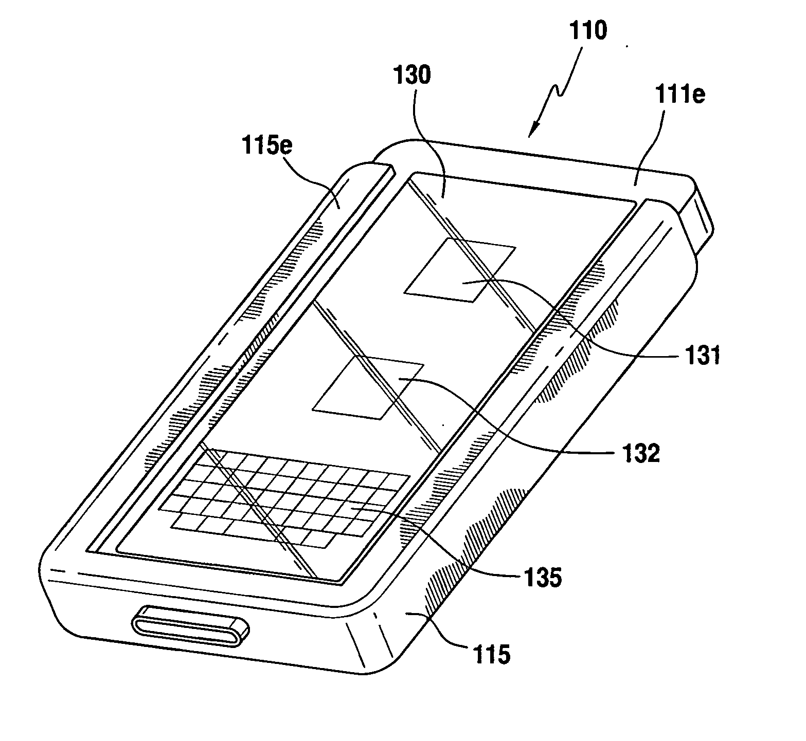
This patent is about a device that can be used to analyze samples for different substances using a special optical assay. The device is powered by a battery and includes a light source that is controlled by the device's software. The sample is placed in a reservoir and then the light source shines light into an optical waveguide, where the light is reflected and directed onto the sample. The device also has a camera to capture the reflected light and memory to store and analyze the data. The device can be used in a variety of settings and can transmit the data to other locations. The technical effect of this invention is to provide a portable and efficient tool for optical testing of samples.

Problems solved by technology

But such methods have not found widespread application in those resource-limited settings and environments primarily because of the complexity and cost of readout hardware for optical assays.
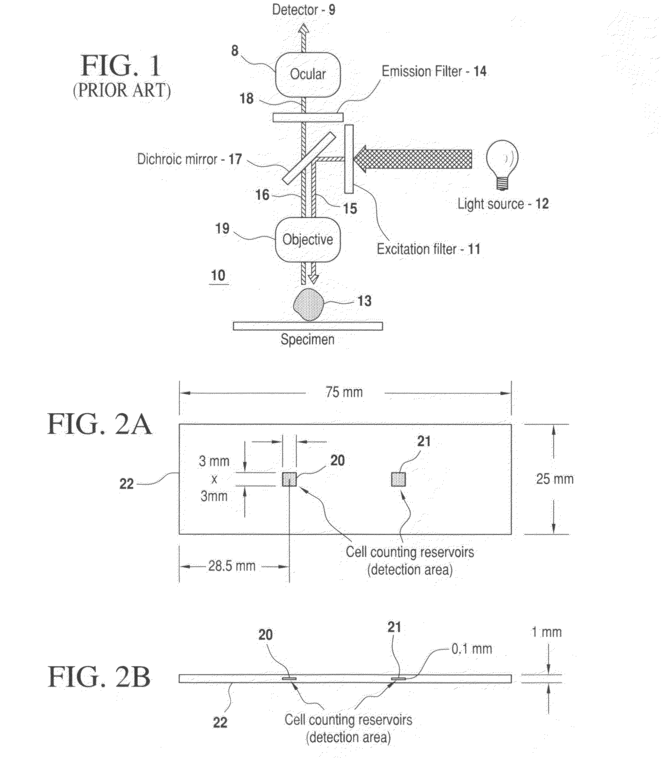
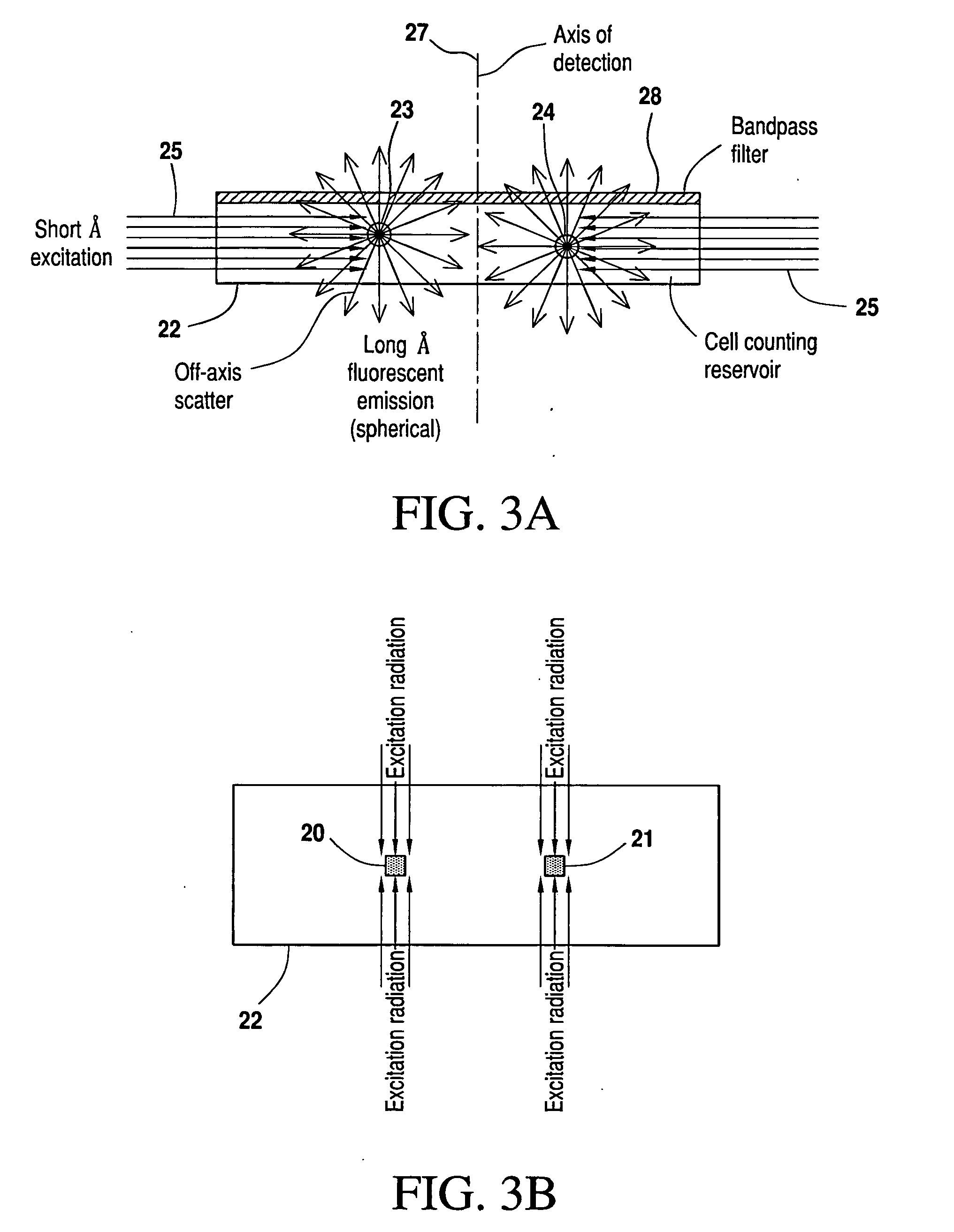
A problem in achieving the desired detection and readout arises from a need to do so amid a substantial background of comparatively shorter wavelength (blue-shifted) radiation used to excite the fluorphores.
Typically, they are relatively fragile, bulky and expensive.
The readout systems excite such fluorescent reporter elements (fluorophores) using broadband sources such as halogen lamps and short arc mercury or xenon gas discharge lamps, which are relatively inefficient from the standpoints of both bandwidth emission and power consumption.
Typical broadband sources employed in prior art readout and detection systems for optical assay of human and animal cells and other analytes are also characterized by relatively large size and considerable heat generation.
The effect of this relatively wide spacing between elements is transmission loss and index mismatch that further exacerbate luminous efficiency of the overall system.
The increasingly rapid pace at which these improvements occur has been dramatic, and has not escaped the attention of practitioners concerning the potential use of such platforms in medical applications.

Method used


Image

  • Compact portable apparatus for optical assay
  • Compact portable apparatus for optical assay
  • Compact portable apparatus for optical assay

Examples


Embodiment Construction

[0052]To overcome the luminous inefficiencies of optical assay apparatus of the prior art, and assist in achieving improved, low-cost, and portable fluorescence readout and detection apparatus, the present invention employs relatively tiny light sources such as light emitting diodes (LEDs). Used in a prototype implementation of the invention, LEDs have demonstrated overall luminous efficiencies approaching 40-45% (see FIG. 7, for example). Unlike typical sources of broadband radiation, LEDs emit photons via the mechanism of electroluminescence, with radiation wavelengths that may be tuned to a relatively narrow range according to the band gap energy of the semiconductor or other organic material used to fabricate the source. This enables matching emission wavelengths with peak absorption wavelengths of various fluorescent reporter elements to eliminate the need for bandpass excitation filters. Indeed, as much as 100% of the wavelength band emitted by a suitably selected LED can be a...


PUM

PropertyMeasurementUnit
Poweraaaaaaaaaa
Transmissionaaaaaaaaaa
Wavelengthaaaaaaaaaa

Abstract

A structure is configured to retain optical diagnostic assay components in a manner that enables them to be synergistically combined or coupled both mechanically and electrically with a conventional mobile electronic device (such as a smartphone), such that the pairing maintains a mutually advantageous relationship to provide a compact portable optical assay apparatus in which the optical assay portion has access to the image sensor, battery power, microprocessor, and data capture, analysis, storage, display and transmission capabilities of the smartphone, and the smartphone portion provides the overall apparatus with features of transportability, user interface, and information storage, analysis and retrieval, and transmission of assay results to a separate site, such as a site of records related to the provider of the sample being assayed. Methods of providing such structure and of performing an optical assay of sample material utilizing such structure are described.

Description

CROSS-REFERENCE TO RELATED APPLICATIONS[0001]This application is related to U.S. Provisional Application No. 61 / 679,300, filed Aug. 3, 2012 by the same inventors herein (“the '300 provisional application”), as to which a claim of priority is made for common subject matter.FIELD OF THE INVENTION[0002]This invention relates generally to optical diagnostic assays of target analytes in sample specimens obtained from human or animal subjects, environmental sources, or foodstuffs, and more particularly to compact portable apparatus for performing the optical assays.BACKGROUND OF THE INVENTION[0003]Optical diagnostic assays are utilized to qualitatively and quantitatively detect chemical, biochemical, biological, cellular, and / or particulate species, sometimes referred to herein as analytes, in biological, clinical, environmental, or foodstuff samples. Performing such assays has been especially helpful, for example, in monitoring growing cell cultures and identifying and counting the numbe...

Claims


Application Information

Patent Timeline
IPC IPC(8): G01N21/63
CPCG01N21/63G01N21/648Y10T29/49002G01N21/6428
Inventor ALT, ECKHARDVYKOUKAL, JODYCOLEMAN, MICHAEL
Owner INGENERON
Learn More