Exhaust gas treatment system

a technology of exhaust gas treatment and exhaust gas, which is applied in the direction of liquid degasification, separation processes, products, etc., can solve the problems of large amount of thermal energy consumed, and achieve the effect of enhancing the removal efficiency of impurities in the exhaust gas and enhancing the thermal efficiency of the power generation system

Inactive Publication Date: 2014-02-13
MITSUBISHI HEAVY IND LTD
View PDF23 Cites 20 Cited by
  • Summary
  • Abstract
  • Description
  • Claims
  • Application Information

AI Technical Summary

Benefits of technology

[0019]According to the present invention, the heat recovered from exhaust gas is used for CO2 removal process and in the boiler. This makes it possible to enhance the thermal efficiency in the power generation system including the exhaust gas treatment system. At the same time, the removal efficiency of impurities in the exhaust gas can also be enhanced.

Problems solved by technology

In the step of regenerating the absorbing solution in particular, a large amount of thermal energy is consumed.

Method used


Image

  • Exhaust gas treatment system
  • Exhaust gas treatment system
  • Exhaust gas treatment system

Examples


first embodiment

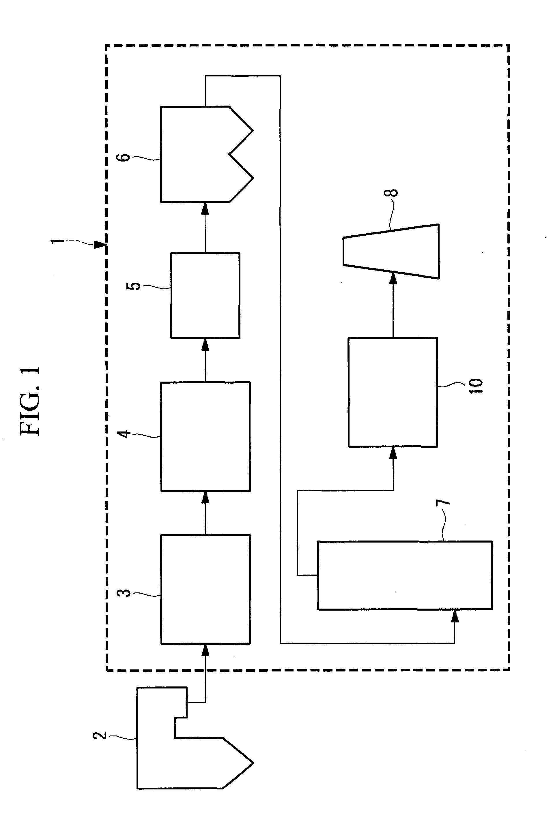
[0027]FIG. 1 is a schematic view of an exhaust gas treatment system according to a first embodiment. An exhaust gas treatment system 1 is placed on a downstream side of a combustion facility such as a boiler 2. Arrows in the drawing indicate the flow of an exhaust gas generated in the boiler 2. The exhaust gas treatment system 1 includes, in order from the gas upstream side, a NOx removal unit 3, an air heater 4, a dry electrostatic precipitator 6, a wet desulfurization unit 7, a CO2 recovery unit 10, and a smokestack 8. In the exhaust gas treatment system 1 of the first embodiment, an exhaust gas heat exchanger 5 is placed between the air heater 4 and the dry electrostatic precipitator 6. The exhaust gas heat exchanger 5 may be placed between the dry electrostatic precipitator 6 and the wet desulfurization unit 7.

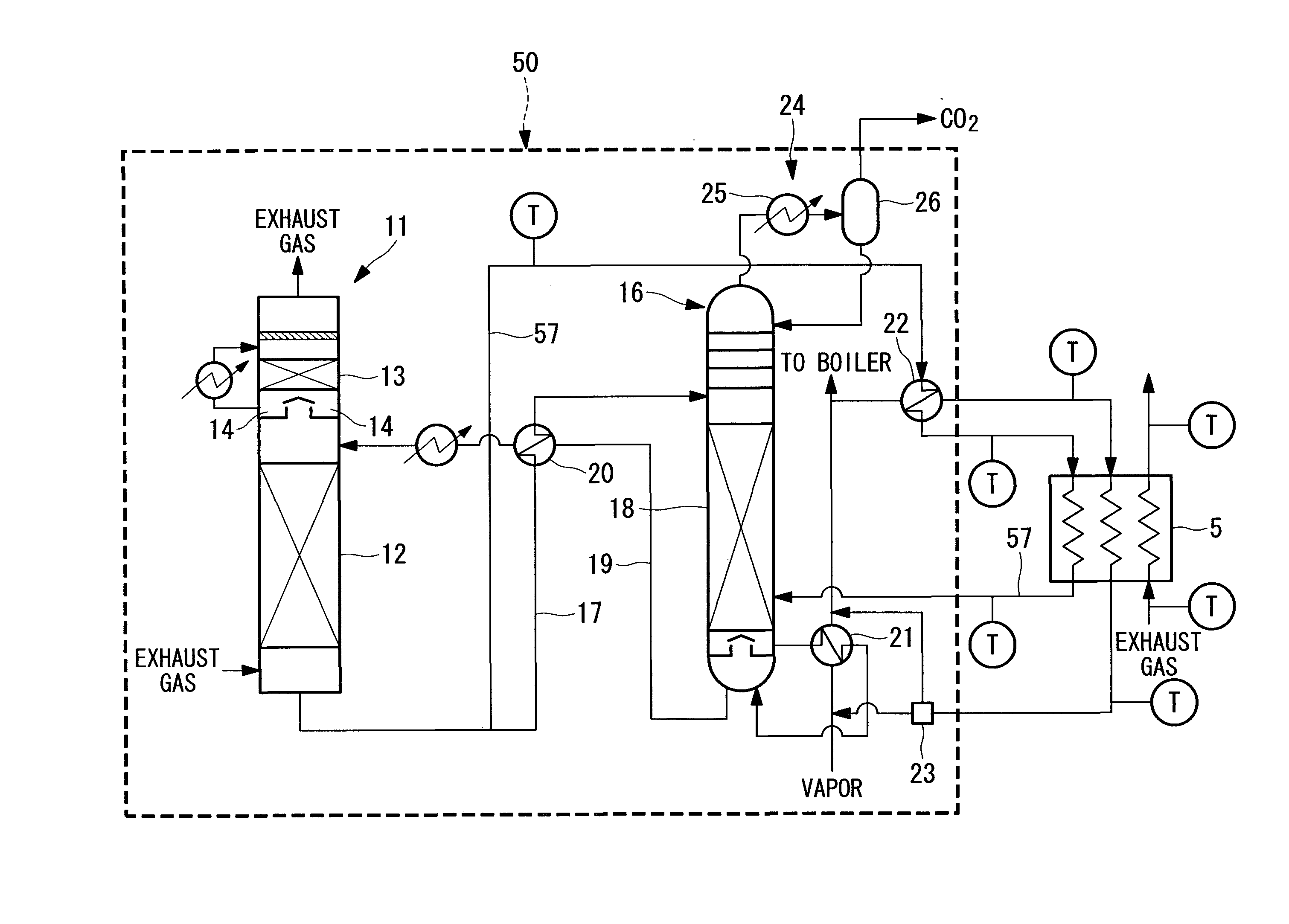
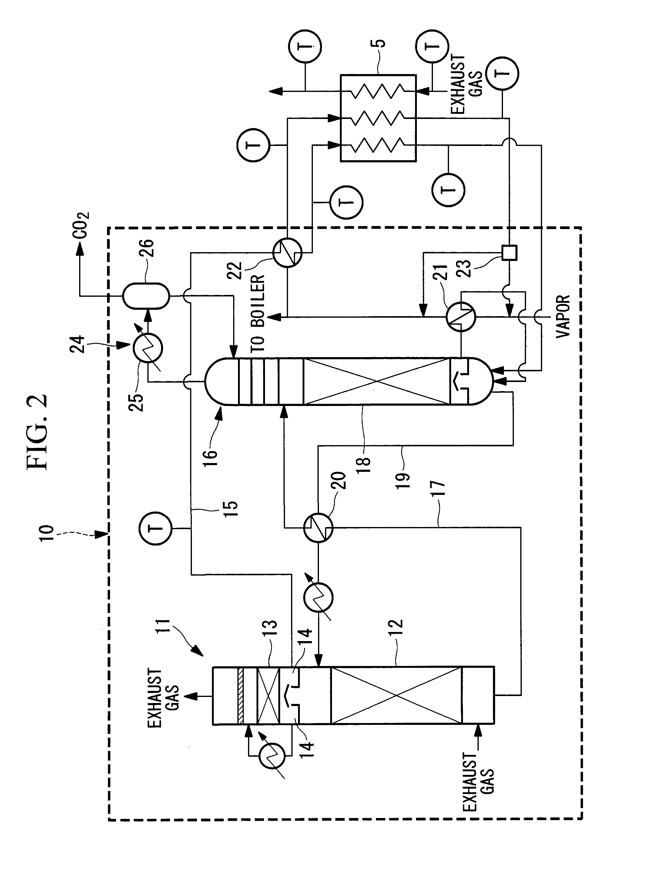
[0028]FIG. 2 is a schematic view for explaining the CO2 recovery unit in the exhaust gas treatment system according to the first embodiment. The CO2 recovery unit 10 of th...

second embodiment

[0050]FIG. 3 is a schematic view for explaining a CO2 recovery unit in an exhaust gas treatment system according to a second embodiment. In FIG. 3, structure components identical to those in FIG. 2 are designated by identical reference signs. The overall structure of the exhaust gas treatment system is identical to that of FIG. 1.

[0051]A CO2 recovery unit 30 is different from that in the first embodiment in the point that all the steam condensate discharged from the reboiler 21 exchanges heat in the heat exchanger 22 and the exhaust gas heat exchanger 5 and then is circulated to the boiler 2.

[0052]As in the first embodiment, process condensate in the CO2 absorption column 11 in the second embodiment is managed in the temperature range from about 40 to 60° C., and the process condensate is heated to 70 to 90° C. by the heat exchanger 22. The steam condensate discharged from the reboiler 21 is cooled to about 75 to 105° C. in the heat exchanger 22.

[0053]The exhaust gas cooled to about...

third embodiment

[0057]FIG. 4 is a schematic view for explaining a CO2 recovery unit in an exhaust gas treatment system according to a third embodiment. In FIG. 4, structure components identical to those in FIG. 2 are designated by identical reference signs. The overall structure of the exhaust gas treatment system is identical to that of FIG. 1.

[0058]A CO2 recovery unit 40 in the third embodiment is structured so that process condensate discharged from the tray 14 below the water washing section 13 of the CO2 absorption column 11 exchanges heat with steam condensate in the heat exchanger 22, and then the process condensate is fed to the absorbing solution regeneration column 16 without passing through an exhaust gas heat exchanger 45. Other structure is similar to that in the first embodiment.

[0059]The process condensate in the CO2 absorption column 11 in the second embodiment is managed in the temperature range from about 40 to 60° C., and the process condensate is heated to 70 to 100° C. by the h...


PUM

PropertyMeasurementUnit
temperatureaaaaaaaaaa

Abstract

There is provided an exhaust gas treatment system including a CO2 recovery unit with further enhanced energy efficiency. An exhaust gas treatment system (1) of the present invention includes: a CO2 recovery unit (10) including a CO2 absorption column (11), an absorbing solution regeneration column (16), and a reboiler (21); and an exhaust gas heat exchanger (5) provided on a gas upstream side of the CO2 recovery unit (10). Heat exchange is performed between process condensate discharged from the CO2 absorption column (11) and steam condensate discharged from the reboiler (21) in a heat exchanger (22). The heated process condensate is fed to the absorbing solution regeneration column (16). Heat exchange is performed between the cooled steam condensate and exhaust gas in the exhaust gas heat exchanger (5) so that the steam condensate is heated while the exhaust gas is cooled.

Description

TECHNICAL FIELD[0001]The present invention relates to an exhaust gas treatment system having a carbon dioxide (CO2) recovery unit placed for removing CO2 from exhaust gas.BACKGROUND ART[0002]In thermal power systems for generating power by combusting fossil fuels such as coal and heavy fuel, a large amount of CO2 is discharged. In recent years, the greenhouse effect by CO2 is pointed out as one of the causes of the global warming. It is necessary, therefore, to take prompt measures to protect the global environment on an international basis. Under these circumstances, there is a trend toward further increase in demand for CO2 discharge control.[0003]In the thermal power systems, there is installed an exhaust gas treatment system including a CO2 recovery unit placed in a flow passage on the downstream side of a boiler. The CO2 recovery unit includes a CO2 absorption column and a CO2 regeneration column as described in Patent Literature 1 and Patent Literature 2. In the CO2 absorption...

Claims


Application Information

Patent Timeline
Patent Type & Authority Applications(United States)
IPC IPC(8): B01D19/00B01D53/14C01B32/50
CPCB01D53/62B01D53/1425B01D53/1475B01D53/343B01D53/78B01D2252/204B01D2257/504B01D2258/0283C01B32/50Y02P20/10Y02P20/151Y02P20/50Y02C20/40
Inventor TSUJIUCHI, TATSUYAHONJO, SHINTAROYONEKAWA, TAKAHITOSUGITA, SATORUITO, MOTOFUMIWU, TIFFANYKAMIJO, TAKASHINAGAYASU, TATSUTOOKAMOTO, TAKUYA
Owner MITSUBISHI HEAVY IND LTD
Why Eureka
Try Eureka