Chromatic sensor and method

a chromatic sensor and sensor technology, applied in the field of chromatic sensor and method, can solve the problems of limited use of optical sensors, limited measurement tasks and specific workpiece properties, and less well suited to other purposes, so as to increase the flexibility of new objectives, and facilitate the coupling of defined illuminations

Inactive Publication Date: 2014-02-13
CARL ZEISS IND MESSTECHN GMBH
View PDF2 Cites 58 Cited by
  • Summary
  • Abstract
  • Description
  • Claims
  • Application Information

AI Technical Summary

Benefits of technology

[0060]In this refinement, between the first lens-element group and the displaceable second lens-element group there is a defined minimum distance that cannot be undershot by the second lens-element group. The clearance makes it possible to accommodate a beam splitter in the optical beam path and/or to introduce the chromatic assembly into the objective between the first lens-element group and the second lens-element group, which makes it possible to couple light in or out “very far at the front”. The refinement increases the flexibility of the new objective since, in particular, it also facilitates the coupling-in of defined illuminations for different sensor principles.
[0061]In further exemplary embodiments, a stripe pattern or some other structured

Problems solved by technology

One disadvantage of known coordinate measuring machines comprising optical sensors heretofore has been that the optical sensors are limited to specific measurement tasks and specific workpiece properties.
Problems can be posed for example by workpieces which have large height differences parallel to the optical axis of the sensor.
Primarily optical sensors therefore have a respective individual optics which is well suited to a specific purpose of use and is less well suited to other purposes.
However, the individual

Method used


Image

  • Chromatic sensor and method
  • Chromatic sensor and method
  • Chromatic sensor and method

Examples


Embodiment Construction

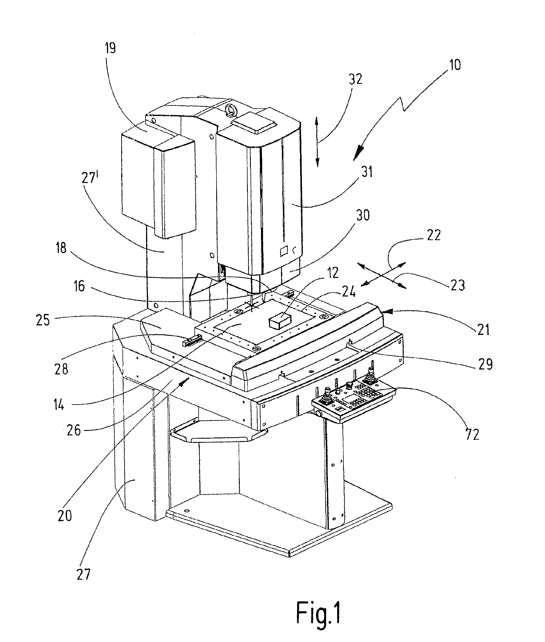
[0076]FIG. 1 shows an apparatus 10 for inspecting a measurement object 12 arranged on a workpiece carrier 14. In the embodiment illustrated, the apparatus 10 is a coordinate measuring machine. The measurement object 12 is measured by means of one or a plurality of optical sensors 18. Selectively, one or a plurality of tactile sensors 16 can additionally also be provided.

[0077]Coordinate measuring machines are generally known in the prior art. They are used, for example in the context of quality assurance, to check workpieces or to determine the geometry of a workpiece completely in the context of so-called “reverse engineering”. Furthermore, a wide variety of further application possibilities are conceivable, thus for example including the additional use for inspecting surfaces.

[0078]In such coordinate measuring machines, different types of sensors can be used to detect the coordinates of a workpiece to be measured. By way of example, sensors that effect tactile measurement are know...


PUM


Abstract

An apparatus for inspecting a measurement object, comprising a workpiece support for supporting the measurement object, and a measuring head carrying an optical sensor. The measuring head and the workpiece support are movable relative to one another. The optical sensor has an objective and a camera for capturing an image of the measurement object along an imaging beam path. The objective has a light entrance opening and a light exit opening, a diaphragm and a multitude of lens-element groups arranged in the objective between the light entrance opening and the light exit opening along a longitudinal axis of the objective. At least two lens-element groups are displaceable parallel to the longitudinal axis. The apparatus also has an illumination device for illuminating the measurement object along an illumination beam path, and a chromatic assembly that can selectively be introduced into the illumination beam path and/or the imaging beam path.

Description

CROSS-REFERENCE TO RELATED APPLICATIONS[0001]This application is a continuation of International PCT application No. PCT / EP2012 / 065477, filed Aug. 7, 2012. This application also claims the priority of U.S. provisional application No. 61 / 680,454, filed Aug. 7, 2012. The entire contents of these priority applications are incorporated herein by reference.BACKGROUND OF THE INVENTION[0002]The present invention relates to an apparatus for inspecting a measurement object, comprising a workpiece support for supporting the measurement object, comprising a measuring head carrying an optical sensor, wherein the measuring head and the workpiece support are movable relative to one another, wherein the optical sensor has an objective and a camera, which is designed to capture an image of the measurement object through the objective along an imaging beam path, wherein the objective has a light entrance opening and a light exit opening, wherein the objective furthermore has a diaphragm and a multit...

Claims


Application Information

Patent Timeline
IPC IPC(8): G01N21/88
CPCG01N21/88G02B21/0016G02B21/025G01N21/8806
Inventor ENGEL, THOMASWINTEROT, JOHANNESKERWIEN, NORBERT
Owner CARL ZEISS IND MESSTECHN GMBH
Why Eureka
Try Eureka