On-fiber optomechanical cavity based sensor

a cavity-based sensor and optomechanical technology, applied in the field of sensors, can solve the problems of bulky and bulky external electronic excitation or actuation systems, and the need for precise b>3/b>-dimensional nanoscale alignment of optical elements, and achieve the effect of significantly increasing the amplitude of its vibrations

Inactive Publication Date: 2014-02-13
TECHNION RES & DEV FOUND LTD
View PDF2 Cites 18 Cited by
  • Summary
  • Abstract
  • Description
  • Claims
  • Application Information

AI Technical Summary

Benefits of technology

[0011]Although the mechanical element can begin vibrating at its resonance frequency without any input power merely as a result of a random positional excursion from its equilibrium rest position, the amplitude of its vibrations can be significantly increased by applying CW laser power, such that the mechanical element undergoes powered self oscillation. The CW laser power thus operates both to excite the mechanical element to vibrate at its resonance frequency, and to detect the frequency of these vibrations by analyzing the optical reflection from the optomechanical cavity.

Problems solved by technology

Although such prior art devices generally utilize nanoscale mechanical elements constructed on-chip, the need for external electronic excitation or actuation systems, which may be bulky, or which may require careful alignment with the on-chip resonator, remains a disadvantage of such passive MEMS devices.
The disadvantage of this set-up is the need for precise 3-dimensional nanoscale alignment of optical elements, and the complexity of supplying the electrical drive to the capacitative driving element in close proximity to the mechanical resonator.
Consequently, this prior art method is complicated by the need to utilize two incident laser beams, and the associated optical elements to avoid interference between them, in order to perform the measurement.

Method used


Image

  • On-fiber optomechanical cavity based sensor
  • On-fiber optomechanical cavity based sensor
  • On-fiber optomechanical cavity based sensor

Examples


Embodiment Construction

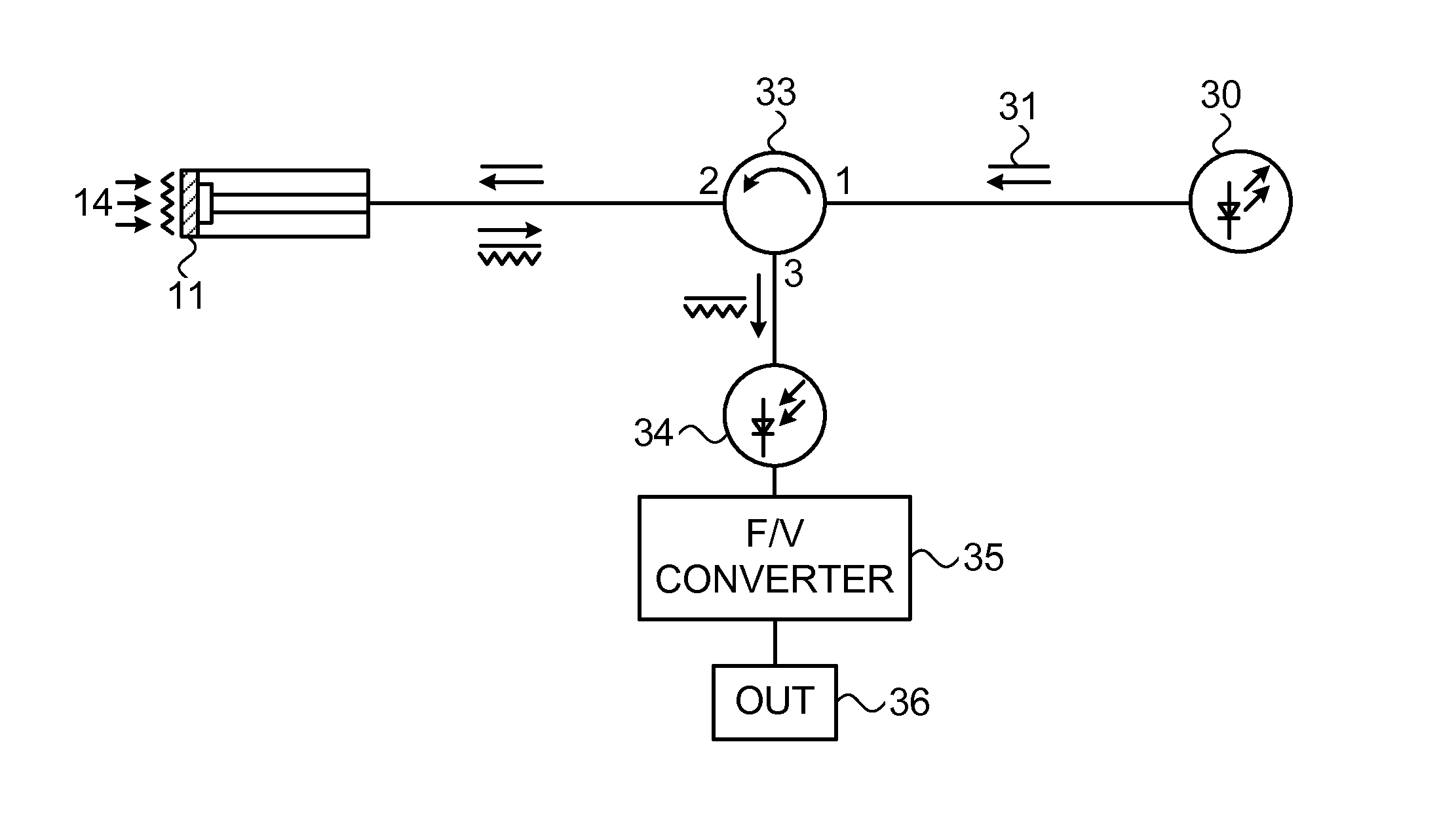
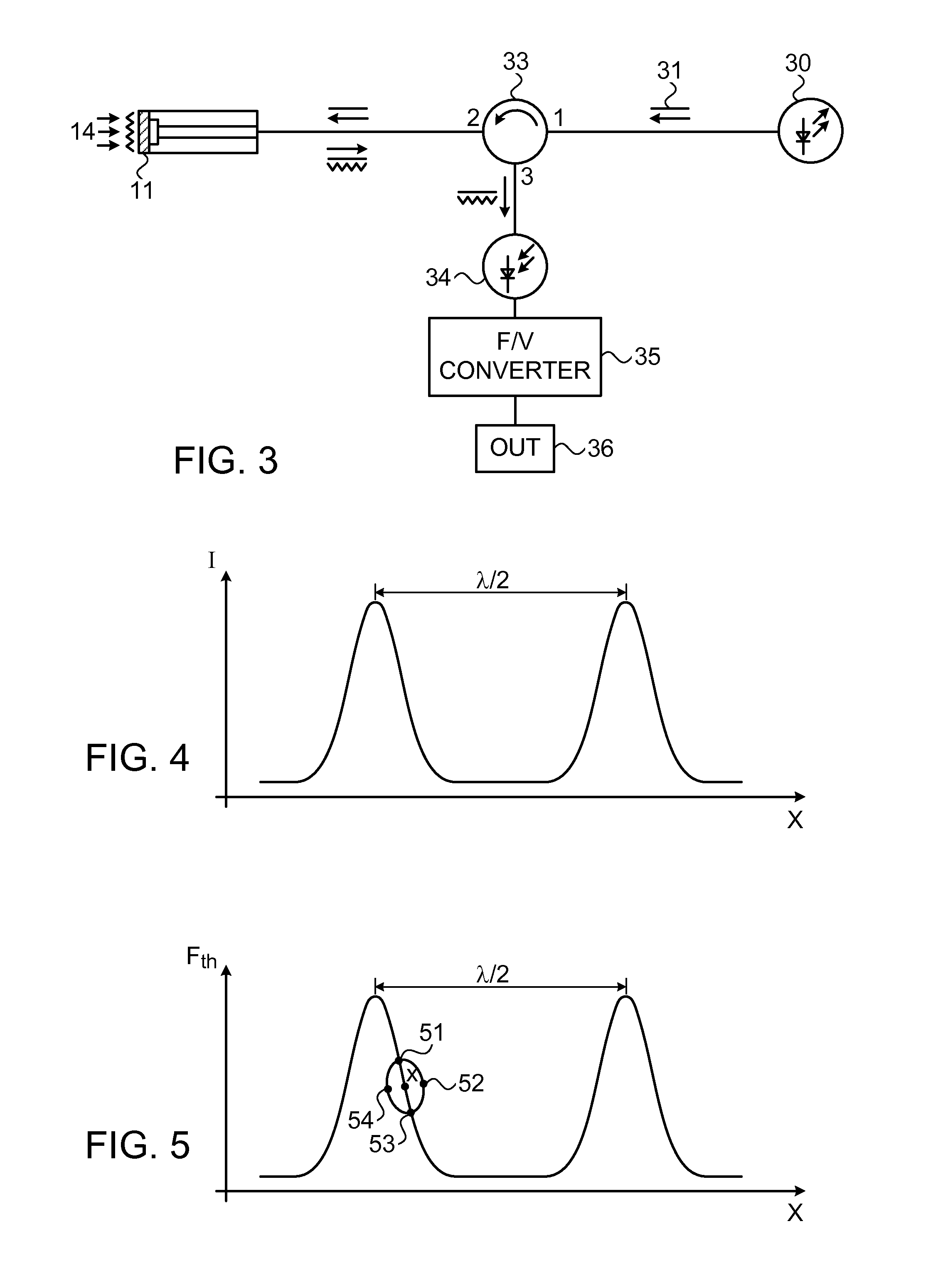
[0032]Reference is now made to FIG. 3, which illustrates schematically a novel exemplary optomechanical measurement system, of the type described in the present disclosure. The system of FIG. 3 differs from that of the prior art in that only a single CW laser 30 is required, thereby substantially reducing the cost of the laser sources required for the system, and the complexity of the detection system. This enables the construction of a lower cost and more compact system, thereby increasing the universality and acceptance of such systems. The single laser source outputs a CW beam 31 at constant power, which is used both for inducing self oscillation of the resonator beam 11, and for measurement of the resonance frequency of the resonator beam, which is used for determining the level of the parameter 14 being measured by the system. The laser source is preferably a diode laser, and if the output is not sufficiently stabilized by the supplied laser / power supply package itself, a level...


PUM


Abstract

A system for measurement of environmental parameters, using an optomechanical cavity in the end of an optical fiber. A single unmodulated CW laser excites the cavity, which has one reflective element fixed within the end of the fiber and the facing reflector being the surface of a mechanical element, supported over the cavity at the end of the fiber so that it can vibrate at its natural resonance frequency. The length of the cavity “vibrates” at the same frequency as the mechanical element, so that the light reflected from the cavity is modulated at that same frequency, and can be readily measured. The resonant frequency of the mechanical element is responsive to the environmental parameter to be measured, either by direct influence on the vibration of the mechanical element, or by means of the element's temperature change as a result of exposure to the environmental parameter.

Description

RELATED APPLICATIONS[0001]The present application claims the benefit under 35 U.S.C.§119(e) of U.S. Provisional Patent Application Ser. No. 61 / 665,325, filed on Jun. 28, 2012, the contents of which is incorporated herein by reference, in its entirely.FIELD OF THE INVENTION[0002]The present invention relates to the field of sensors based on the frequency of oscillation of an optomechanical cavity fabricated on the tip of an optical fiber, especially for use in sensing environmental conditions.BACKGROUND OF THE INVENTION[0003]The advancement in the MEMS industry has enabled the development of mechanical resonators to measure physical parameters such as temperature, mass, pressure, radiation, stress, acceleration and chemical changes with unprecedented sensitivity. A conventional MEMS system used to measure such a physical parameter consists of a transducer to actuate the mechanical system into vibration and a detector to sense changes in this resonance frequency of the mechanical syst...

Claims


Application Information

Patent Timeline
Patent Type & Authority Applications(United States)
IPC IPC(8): G02B6/42
CPCG02B6/42G01D5/35367G01D5/35354
Inventor DHAYALAN, YUVARAJBACHAR, GILBASKIN, ILYASHTEMPLUCK, OLEGBUKS, EYAL
Owner TECHNION RES & DEV FOUND LTD
Why Eureka
Try Eureka