Centrifuge and power controlling apparatus

a centrifuge and power control technology, applied in centrifuges, power conversion systems, ac-ac conversion, etc., can solve the problems of inability to automatically treat the switching for each country, work takes time, operation errors, etc., to prolong the life of the driving circuit of the chiller, suppress the noise level thereof, and operate stably

Active Publication Date: 2014-02-13
EPPENDORF HIMAC TECH CO LTD
View PDF10 Cites 9 Cited by
  • Summary
  • Abstract
  • Description
  • Claims
  • Application Information

AI Technical Summary

Benefits of technology

[0043]According to a seventh aspect, it is possible to make a life of the driving circuit of the chiller longer, since the voltage switching unit is connected to the chiller through a semiconductor relay which controls the turning on or off of power to the chiller, accordingly, the chiller is not directly turned on or off at a mechanical contact such as a relay, or the like.
[0044]According to an eighth aspect, it is possible for the chiller to stably operate when starting up, and to suppress the noise level thereof, since the semiconductor relay is a solid state relay with the zero-crossing detection unit built-in, and it is possible to perform the switching to the on state of the output voltage when it is 0 V, and the starting current of the chiller is stable.

Problems solved by technology

In addition, regarding the power supply frequency, there are countries in which 50 Hz and 60 Hz are used together, like Japan, there are also cases where it is not possible to automatically treat the switching for each country.
Such work takes time, and may have operation error or the like.
In addition, there is a problem in that a local installation worker may forget the task of switching the transformer tap connection.
In this system, it is advantageous in that the chiller can be driven regardless of the power supply frequency, however, on the other hand, it is disadvantageous in that the driving circuit becomes complicated, large, and expensive.
There is a concern that a mechanical on / off operation such as a relay may damage the contact, and the life of the centrifuge may be shortened, since several tens of amperes of starting current flow over several cycles, when starting up the centrifuge by turning on the chiller.

Method used


Image

  • Centrifuge and power controlling apparatus
  • Centrifuge and power controlling apparatus
  • Centrifuge and power controlling apparatus

Examples


first embodiment

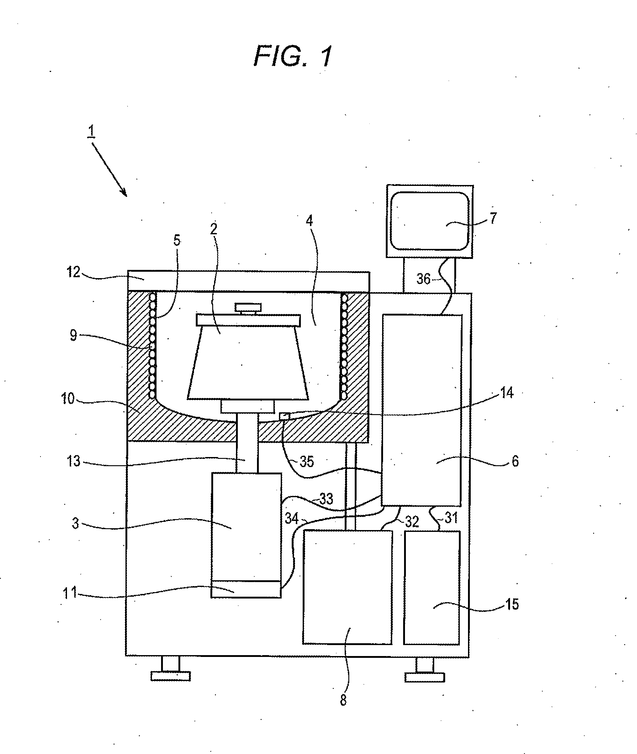
[0051]Hereinafter, embodiments of the invention will be described with reference to the drawings. In addition, in the drawings in below, the same portions will be denoted by the same reference numerals, and descriptions thereof will be omitted. FIG. 1 is a cross-sectional view which shows an outline of the overall configuration of the centrifuge 1 according to the embodiment of the invention.

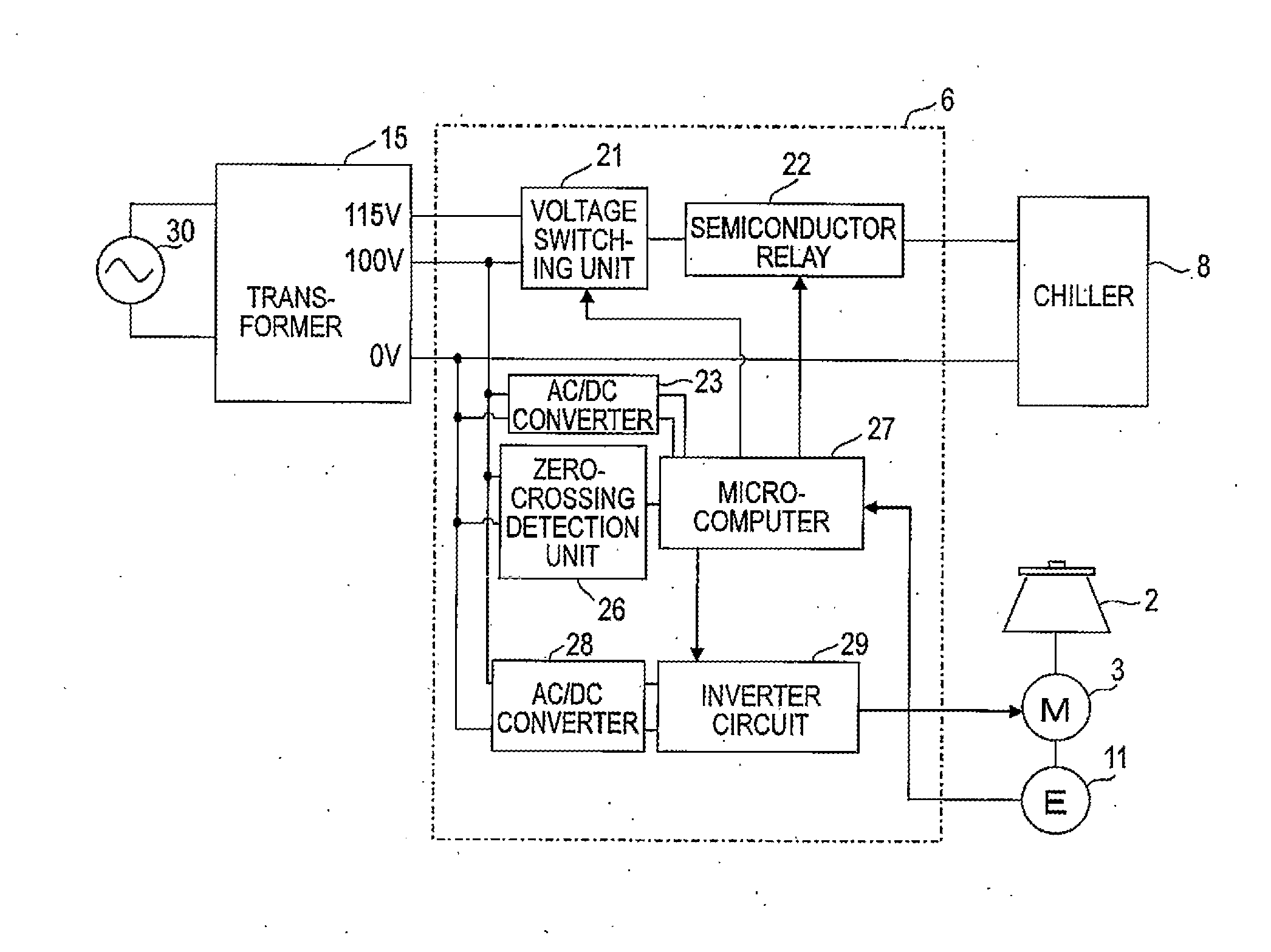
[0052]The centrifuge 1 is provided with a rotor chamber 4 in the main body, and includes an encoder 11 on the lower side of the rotor chamber 4, which detects a motor 3 as a driving source, and the number of revolutions of the motor 3. A rotor 2 is detachably mounted at the tip end portion of an output shaft (motor shaft) 13 which extends to the inside of a bowl 5, which is above the motor 3. The bowl 5 is a container of a substantially cylindrical shape with a circular opening portion at the top portion, and defines the rotor chamber 4. The opening portion at the top of the bowl 5 is configured...


PUM


Abstract

A centrifuge includes a rotor which accommodates a sample, a motor which rotationally drives the rotor and a chiller which cools a rotor chamber, and is provided with a transformer which has a plurality of secondary side taps, converts an AC voltage which is input from a primary side to a plurality of voltages, and outputs, and a voltage switching unit which is connected to the plurality of secondary side taps of the transformer, selects any one of outputs of the secondary side taps, and outputs to the chiller. The microcomputer controls the voltage switching unit corresponding to the power supply frequency which is determined using the output of the zero-crossing detection circuit, and supplies the desired driving voltage to the chiller.

Description

TECHNICAL FIELD[0001]The present invention relates to a centrifuge which rotates a rotor at high speed, and particularly relates to a centrifuge in which switching of a driving voltage to a chiller by determining a power supply frequency is performed automatically, and a power controlling apparatus for driving a device.BACKGROUND ART[0002]In the related art, a centrifuge is provided with a chiller in which a compressor that operates using a commercial power supply is mounted. The centrifuge is configured such that when centrifugally separating a sample to be separated accommodated by the rotor through rotating at high speed, the inside of the rotor chamber is cooled through driving a chiller, and controls the temperature of the sample to be a desired target temperature, in order to prevent the temperature of the sample from increasing due to frictional heat between the air in the rotor chamber and the rotor.[0003]Specifically, the temperature in the rotor chamber is sensed using a t...

Claims


Application Information

Patent Timeline
Patent Type & Authority Applications(United States)
IPC IPC(8): B04B9/02
CPCB04B9/02B04B9/10B04B13/00B04B15/02H02M1/10H02M5/458
Inventor OSAWA, HIDETAKAMAENO, KOUSUKETAKAHASHI, HIROYUKI
Owner EPPENDORF HIMAC TECH CO LTD
Why Eureka
Try Eureka