Method for calibration and qa

a positioning system and calibration method technology, applied in the field of radiotherapy, can solve the problems of positioning errors, radiation to reach tissue-destructive levels, etc., and achieve the effect of secure keeping still during image acquisition, large deviation, and large positioning errors

Inactive Publication Date: 2014-02-13
ELEKTA AB
View PDF0 Cites 8 Cited by
  • Summary
  • Abstract
  • Description
  • Claims
  • Application Information

AI Technical Summary

Benefits of technology

[0018]The present invention is based on the insight that there are angular variations or deviations between a coordinate system of an imaging system, such as a CBCT system, and the stereotactic coordinate system that defines the treatment positions due to, for example, manufacturing tolerances. The CBCT system is used to capture images of the patient and the treatment volume and the reconstructed image of the treatment volume must therefore relate to the focus position of the therapy unit and the patient positioning system position. The CBCT coordinates are physically offset from the focus and it is not possible to mechanically know from tolerances what position the CBCT system has in relation to the focus position. Thus, these variations or deviations cause positioning errors when the patient is translated into the radiation therapy unit for a treatment. Even a very small sinusoidal error may result in large deviations if the patient is translated a large distance and may hence cause large positioning errors. These insights have lead to the invention and the idea of determining and compensating for the deviations between a coordinate system of the imaging system, such as a CBCT system, and the stereotactic coordinate system

Problems solved by technology

However, tissue destruction occurs where the radiation beams from all radiation sources intersect or converge, causing the radiation to reach tissue-destructive levels.
Such angular variations between the CBCT coordinate s

Method used


Image

  • Method for calibration and qa
  • Method for calibration and qa
  • Method for calibration and qa

Examples


Embodiment Construction

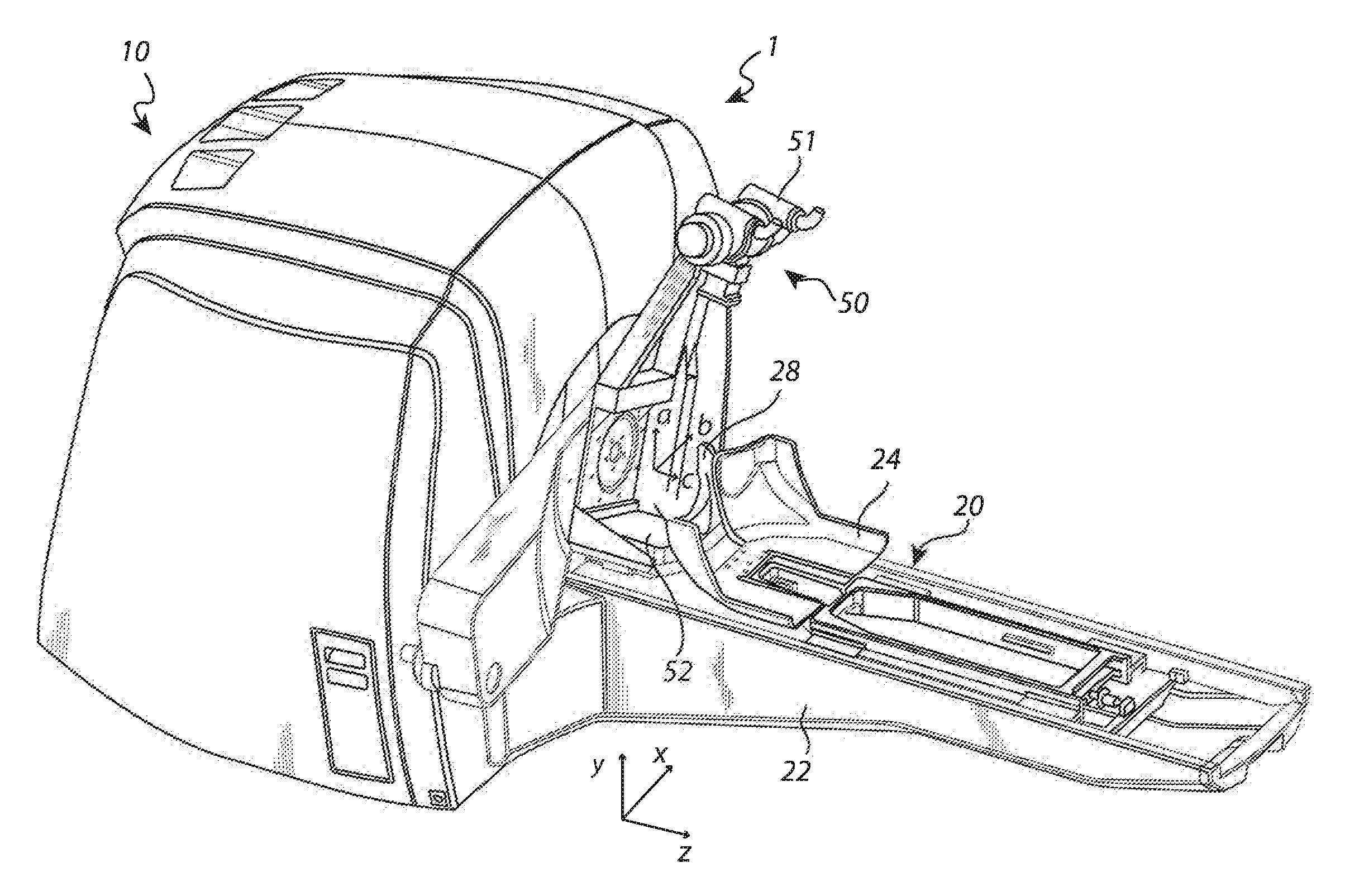
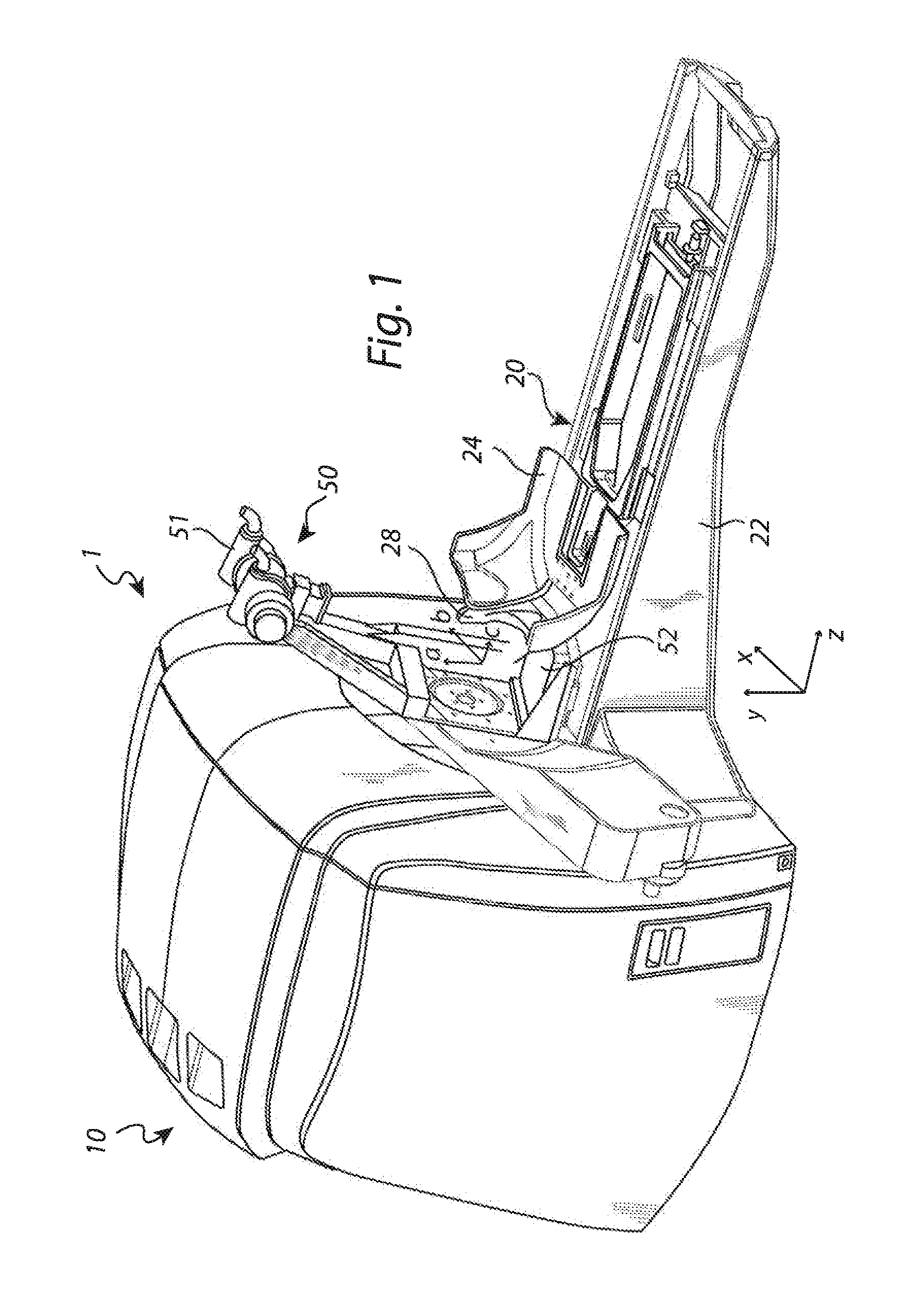
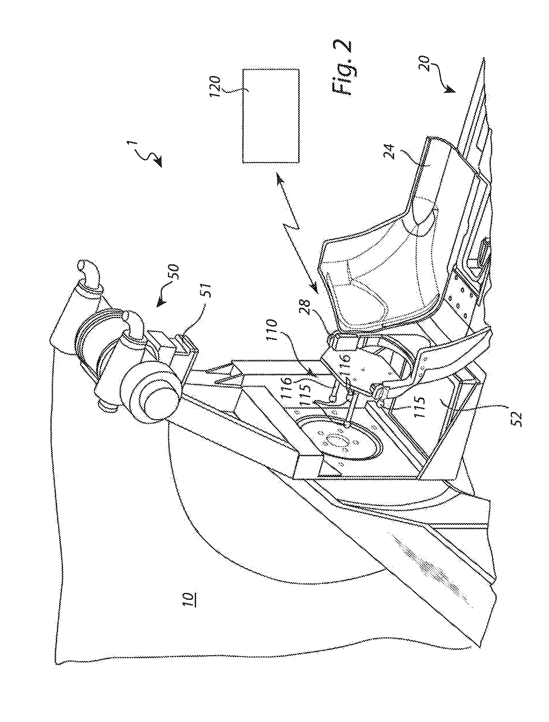
[0037]With reference to FIG. 1, a radiation therapy system 1 for which the present invention is applicable comprises a radiation unit 10 and a patient positioning unit 20. In the radiation unit 10, there are provided radioactive sources, radioactive source holders, a collimator body, and external shielding elements. The collimator body comprises a large number of collimator channels directed towards a common focus point, in a manner as is commonly known in the art.

[0038]The collimator body also acts as a radiation shield preventing radiation from reaching the patient other than through the collimator channels. Examples of collimator arrangements in radiation therapy systems applicable to the present invention can be found in WO 2004 / 06269 A1, which is hereby incorporated by reference. However, the present invention is also applicable to radiation therapy systems using other arrangements for collimating radiation into a fixed focus point, such as is disclosed in U.S. Pat. No. 4,780,8...


PUM


Abstract

The present invention relates to the field of radiation therapy. In particular, the invention concerns a method of calibrating a positioning system in a radiation therapy system comprising a radiation therapy unit having a fixed radiation focus point. The method comprises the steps of: —releasably attaching a calibration tool to the fixation arrangement; —performing an image scanning procedure with the imaging system; —determining a position of the calibration tool in a coordinate system related to the imaging system; and —calculating a position difference between the determined position of the calibration tool in the coordinate system related to the imaging system and a position of the calibration tool in the stereotactic fixation unit coordinate system, thereby determining a relationship between the coordinate system related to the imaging system and the position of the calibration tool in the stereotactic fixation unit coordinate system.

Description

FIELD OF THE INVENTION[0001]The present invention relates to the field of radiation therapy. In particular, the invention concerns a method of calibrating a positioning system in a radiation therapy system comprising a radiation therapy unit having a fixed radiation focus point.BACKGROUND OF THE INVENTION[0002]The development of surgical techniques has made great progress over the years. For instance, for patients requiring brain surgery, non-invasive surgery is now available which is afflicted with very little trauma to the patient.[0003]One system for non-invasive surgery is sold under the name of Leksell Gamma Knife®, which provides such surgery by means of gamma radiation. The radiation is emitted from a large number of fixed radioactive sources and is focused by means of collimators, i.e. passages or channels for obtaining a beam of limited cross section, towards a defined target or treatment volume. Each of the sources provides a dose of gamma radiation which is insufficient t...

Claims


Application Information

Patent Timeline
IPC IPC(8): G06F19/00G16H20/40G16H30/40
CPCG06F19/3481G06F19/3412A61N5/1075A61N2005/1076G16H40/40G16H30/40G16H20/40
Inventor CARLSSON, PER
Owner ELEKTA AB
Why Eureka
Try Eureka