
Solar Power Distribution System

a technology of solar energy and distribution system, applied in the direction of dc network circuit arrangement, dc power distribution plant power efficiency challenges, dc power distribution plant application losses, etc., to achieve the effect of increasing the energy efficiency of the system and maximizing the operational range of the converter

Inactive Publication Date: 2014-02-20
RENEWABLE ENERGY SOLUTION SYST
View PDF12 Cites 9 Cited by
  • Summary
  • Abstract
  • Description
  • Claims
  • Application Information

AI Technical Summary

Benefits of technology

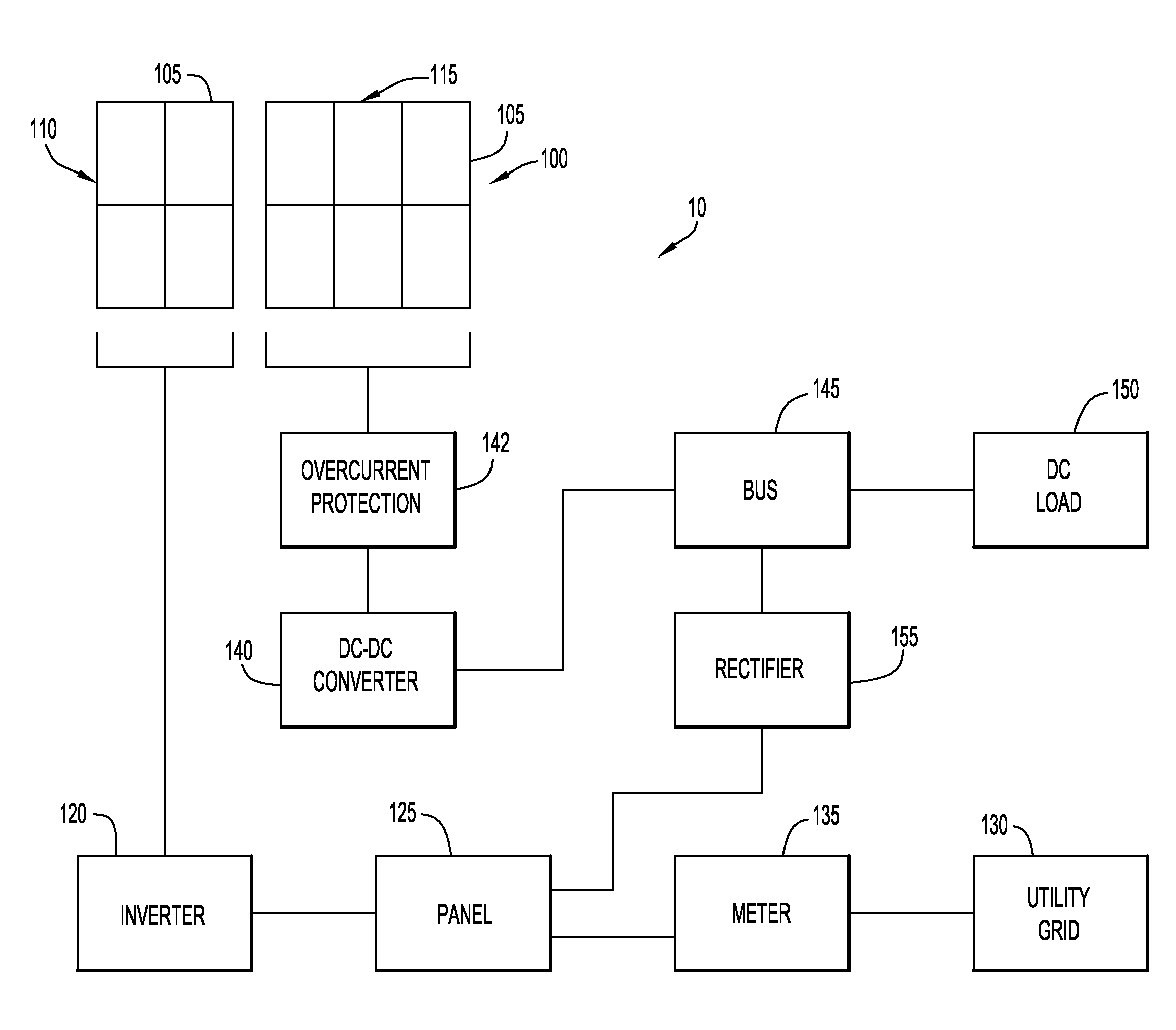
[0008]In another embodiment, the system includes a PV array electrically coupled to a power management device configured to condition the variable voltage generated by the array. Specifically, the power management device may be coupled to the DC-DC converter that supplies the DC load. The power management device is configured to continuously monitor the input and output voltages of the converter, maximizing the operational range of the converter thereby increasing the energy efficiency of the system.

Problems solved by technology

Connecting photovoltaic panels to the power system of the DC power distribution plant presents power efficiency challenges.
Due to the variable voltages produced by photovoltaic panels, this traditional method of inverting DC to AC and then back to DC presents extensive losses in DC plant applications.
Specifically, systems used in these applications are generally inefficient because of constant heat losses occurred during transitions from DC to AC, and then back to DC.

Method used


Image

  • Solar Power Distribution System
  • Solar Power Distribution System
  • Solar Power Distribution System

Examples


Embodiment Construction

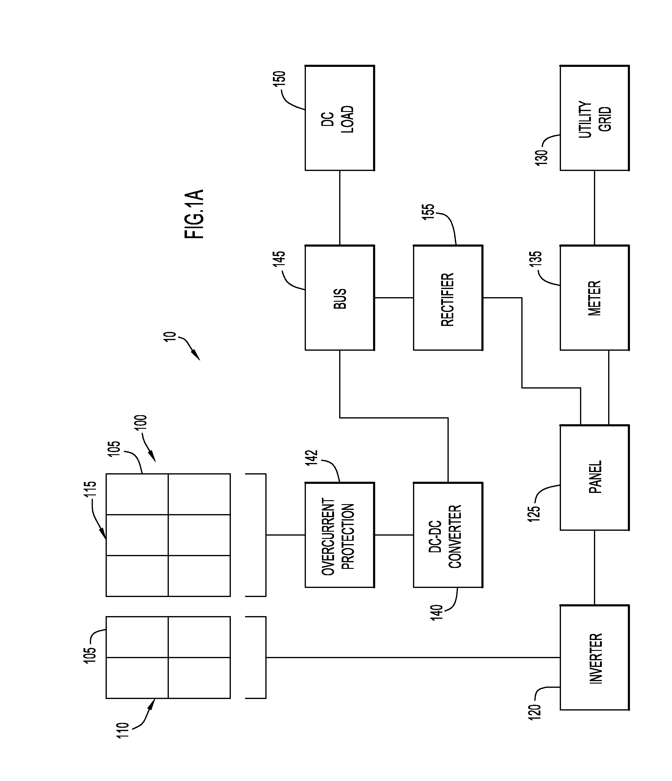
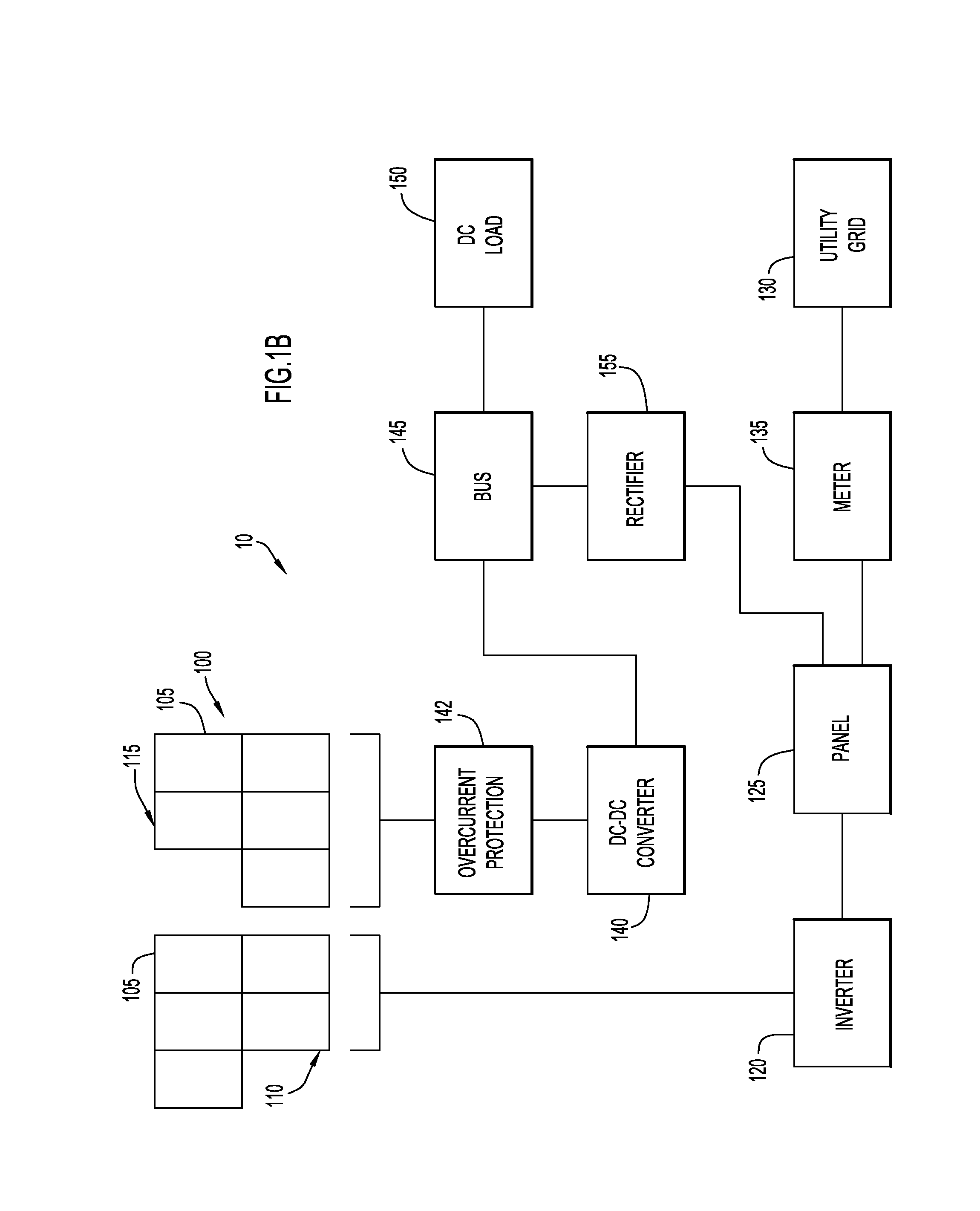
[0016]FIGS. 1A and 1B illustrate a direct current (DC) power management system 100 supported by solar power in accordance with an embodiment of the invention. The DC power management system may be implemented in any DC plant including. By way of example, the DC power management system may be utilized within a telecommunications site operable to facilitate wireless network access. For example, the site may be a telecommunications tower, a telephony base station, a wireless network access base station, a wireless email base station, and / or the like. By way of further example, the cell site may be operated by a mobile telephony service provider. Generally, cell site is configured to provide a network interface for mobile devices. The cell site and mobile devices may communicate using any wireless protocol or standard. These include, for example, Global System for Mobile Communications (GSM), Time Division Multiple Access (TDMA), Code Division Multiple Access (CDMA), Orthogonal Frequenc...


PUM


Abstract

The present invention is directed toward a solar power system including an array of photovoltaic panels. The photovoltaic array may include a first module electrically coupled to an AC load and a second module electrically coupled to a DC load. The array may be reconfigured such that individual panels may be transferred from the first module to the second module, and vice versa. The arrays may generate power that is selectively distributed to direct current and alternating current power loads. The system further includes a power management device effective to maximize the power generation of the second module.

Description

CROSS-REFERENCE TO RELATED APPLICATIONS[0001]The present application claims priority under 35 U.S.C. §120 to U.S. Nonprovisional application Ser. No. 12 / 887,321, entitled “Solar Power Distribution System” filed Sep. 21, 2010, which claims priority from U.S. Provisional Application No. 61,244,290, entitled “Solar Power Distribution System” filed Sep. 21, 2009 the disclosures of which are incorporated herein by reference in their entirety.FIELD OF THE INVENTION[0002]The present invention relates to a solar power generation system and, in particular, to a system configured to maximize the energy efficiency of a direct current power distribution plant supported by solar power.BACKGROUND OF THE INVENTION[0003]Direct current (DC) power distribution plants include power systems that generally employ rectifiers that generate a direct current (DC) voltage from an alternating current (AC) power source. Distribution modules include circuit breakers that connect the rectifiers to loads and that...

Claims


Application Information

Patent Timeline
Patent Type & Authority Applications(United States)
IPC IPC(8): H02J4/00
CPCH02J4/00H02J1/06H02J7/35H02J2300/26H02J3/381Y02E10/56
Inventor RAGAVANIS, CHRIS J.
Owner RENEWABLE ENERGY SOLUTION SYST
Learn More