Driving device and method for driving a load, in particular an LED assembly

a technology of led assembly and driving device, which is applied in the direction of electroluminescent light sources, semiconductor lamp usage, electric lighting sources, etc., can solve the problems of inductive components adding to the cost and physical volume of the system, no light output, flickering light output and voltage misalignment, etc., to achieve better compatibility with phase-cut dimmers, reduce the value range of series capacitors, and create less glitches

Active Publication Date: 2014-02-20
KONINKLIJKE PHILIPS ELECTRONICS NV
View PDF3 Cites 30 Cited by
  • Summary
  • Abstract
  • Description
  • Claims
  • Application Information

AI Technical Summary

Benefits of technology

[0041]Further, switch control methods are provided which allow for a larger series capacitor value range, create less glitches, have better compatibility with phase-cut dimmers, and avoid overcharging the switched series capacitor and too high node voltages.

Problems solved by technology

However, the LED's non-linear (near exponential) I-V curve, its low operation voltage (a few volt) and its fast response of the current-to-light-output transfer create a number of problems when the lamp is to be supplied from mains voltage (e.g. 115 V AC or 230 V AC), including light output flicker and voltage misalignment.
Especially the inductive components add to the cost and physical volume of the system.
All of these TLD systems have one common disadvantage: if the (rectified) mains voltage falls below the voltage of the “shortest” high-voltage LED string, there is no light output.
Another disadvantage is the reduced efficiency.
Since the number of taps is normally limited (in order to avoid very high complexity and part count for the driver circuit) this voltage step and hence the mismatch and losses can be quite significant, resulting in driver efficiencies of approximately 80%.
When such a circuit is used with a dimmer in the mains supply branch a new problem arises.
During the time that the fill-in capacitor is used to supply the energy, the current drawn from mains is substantially zero as the diodes in the mains bridge rectifier are reverse-biased, and this may lead to improper operation of the internal timing circuit of the dimmers, e.g. two-wire dimmers such as TRIAC dimmers.
This results in no or incorrect activation of the power switch in the dimmer and leads to no or unstable light output (light flicker), which of course is unwanted.
The addition of the fill-in capacitor helps to maintain light output around the zero crossing of the mains voltage (flicker reduction), but creates problems with dimmers such as multi-triggering as its discharging current does not pass through the mains branches.

Method used


Image

  • Driving device and method for driving a load, in particular an LED assembly
  • Driving device and method for driving a load, in particular an LED assembly
  • Driving device and method for driving a load, in particular an LED assembly

Examples


Embodiment Construction

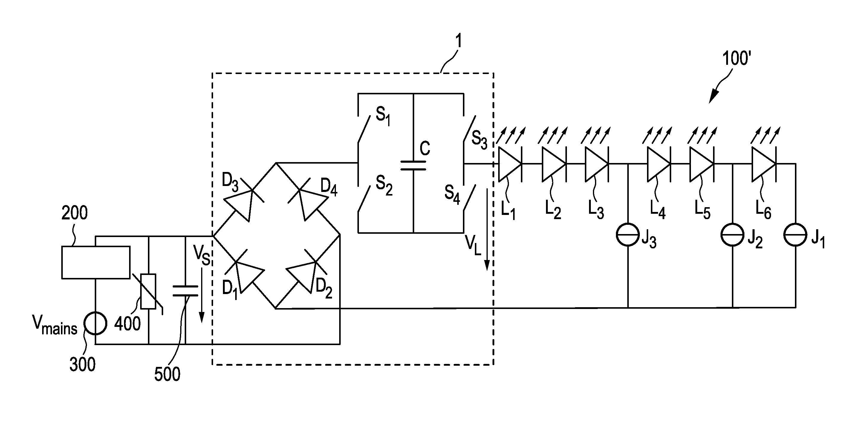
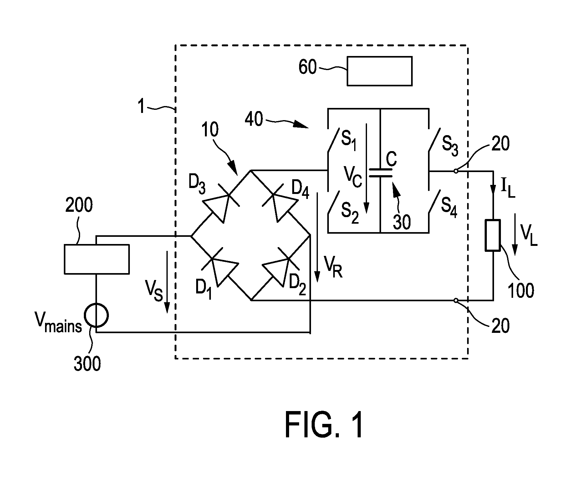
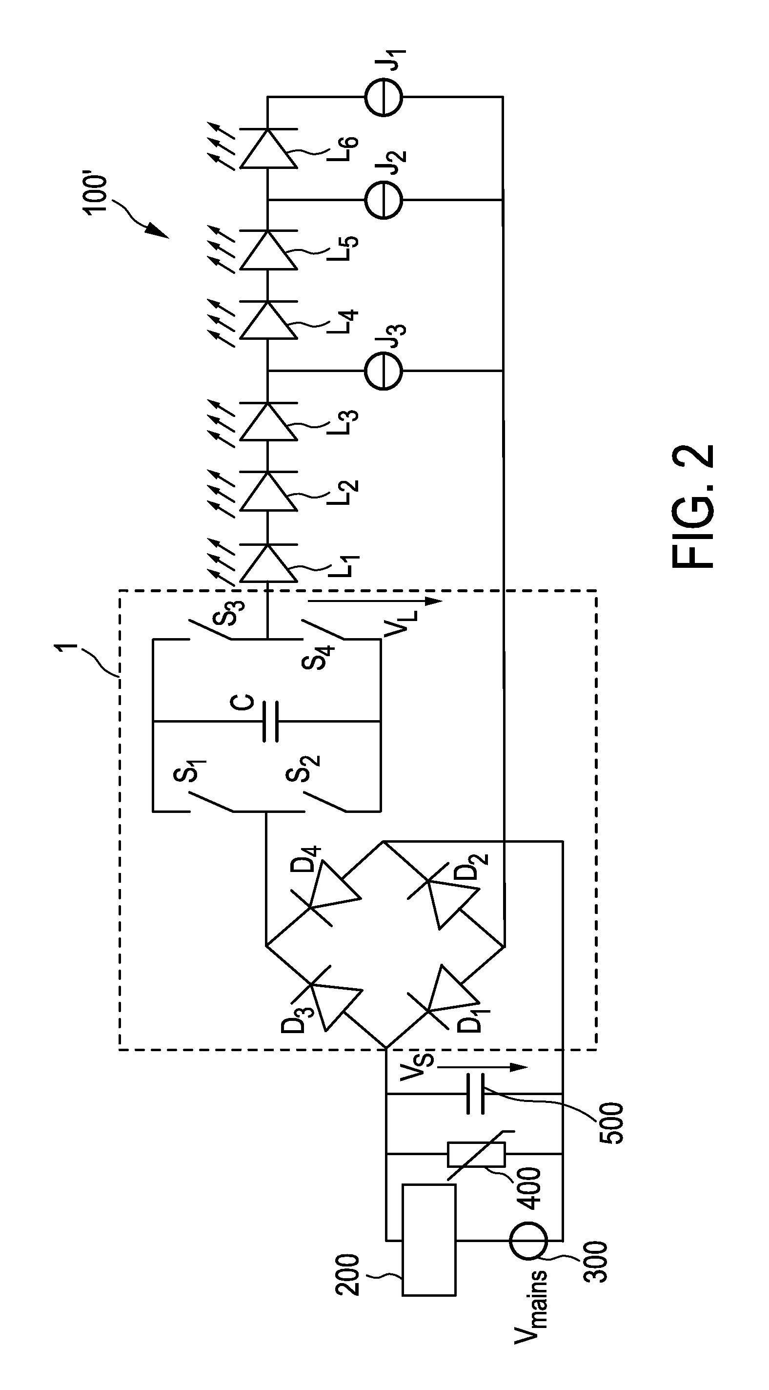
[0081]FIG. 1 shows a first embodiment of a driver device 1 (also called driver circuit) for driving a load 100, in particular an LED assembly comprising one or more LEDs, according to the present invention. Said driver device 1 comprises a rectifier unit 10 for generating a rectified supply voltage VR by rectifying a received AC supply voltage VS, which is in this embodiment supplied by a (external) dimmer 200 coupled to a (external) mains voltage supply 300 providing a mains voltage Vmains. The drive voltage VL for driving the load 100 is provided at a pair of load terminals 20. A capacitive storage unit 30 is coupled between rectifier unit 10 and the load 100 for storing electrical energy provided by the rectifier unit 10 and providing electrical energy to load 100. A bridge switching unit 40 is coupled between the rectifier unit 10 and the load 100 for switching the capacitive storage unit 30 into a load current path from the rectifier unit 10 to the load 100 with a desired polar...


PUM


Abstract

Driver device and a corresponding driving method for driving a load, in particular an LED assembly comprising one or more LEDs. To provide a better performance, better cost-efficiency, improved power factor and reduced losses, a driver device (1,1′, 2, 2′) is provided comprising a rectifier unit (10) for rectifying a received AC supply voltage (VS), load terminals (20) for providing a drive voltage (VL) and/or a drive current (IL) for driving said load, a capacitive storage unit (30) coupled between said rectifier unit and said load terminals for storing electrical energy provided by said rectifier unit and providing electrical energy to said load, and a bridge switching unit (40) coupled between said rectifier unit and said load for switching said capacitive storage unit into a load current path from said rectifier unit to said load terminals with a desired polarity and for switching said capacitive storage unit out of said load current path.

Description

FIELD OF THE INVENTION[0001]The present invention relates to a driver device and a corresponding driving method for driving a load, in particular an LED assembly comprising one or more LEDs. Further, the present invention relates to a lighting apparatus.BACKGROUND OF THE INVENTION[0002]The Light Emitting Diode (LED) is revolutionizing the lighting world. Its high and still increasing luminous efficacy, its long lifetime, its small form factor, its low weight, its ruggedness, its ease of manufacturing, etc., form driving forces for the lighting industry to move from the incandescent lamp to the LED lamp. However, the LED's non-linear (near exponential) I-V curve, its low operation voltage (a few volt) and its fast response of the current-to-light-output transfer create a number of problems when the lamp is to be supplied from mains voltage (e.g. 115 V AC or 230 V AC), including light output flicker and voltage misalignment.[0003]Ideally the LEDs have to be supplied with a direct curr...

Claims


Application Information

Patent Timeline
Patent Type & Authority Applications(United States)
IPC IPC(8): H05B33/08H05B44/00
CPCH05B33/0815H05B45/40H05B45/48Y02B20/30H05B45/38H05B45/59
Inventor RADERMACHER, HARALD JOSEF GUNTHERBLANKEN, PIETER GERRITQIU, YIFENGTAO, HAIMINVAN LANGEVELDE, RONALDKURT, RALPH
Owner KONINKLIJKE PHILIPS ELECTRONICS NV
Why Eureka
Try Eureka