Sensors

a technology of sensors and microstructures, applied in the field of sensors, can solve the problems of destructive microstructure analysis techniques, time-consuming, costly, etc., and achieve the effect of not allowing continuous monitoring, and reducing the number of sensors

Active Publication Date: 2014-02-20
UNIV OF MANCHESTER
View PDF4 Cites 11 Cited by
  • Summary
  • Abstract
  • Description
  • Claims
  • Application Information

AI Technical Summary

Problems solved by technology

Conventional microstructural analysis techniques are destructive and involve removing samples for analysis from, for example, the end of a coil of the processed material.
This is time-consuming, costly, does not allow continuous monitoring, and assesses only a small fraction of the material processed.
Furthermore, if a coil is placed in the vicinity of the steel being processed, this results in a change in impedance measurements for the coil because conductivity and permeability are influenced by the steel's microstructure.
However, problems exist in monitoring in real-time the electromagnetic properties of metals during processing.
Many problems result from the environmental conditions associated with metal processing, such as heat, moisture, humidity, etc.

Method used


Image

  • Sensors
  • Sensors
  • Sensors

Examples


first embodiment

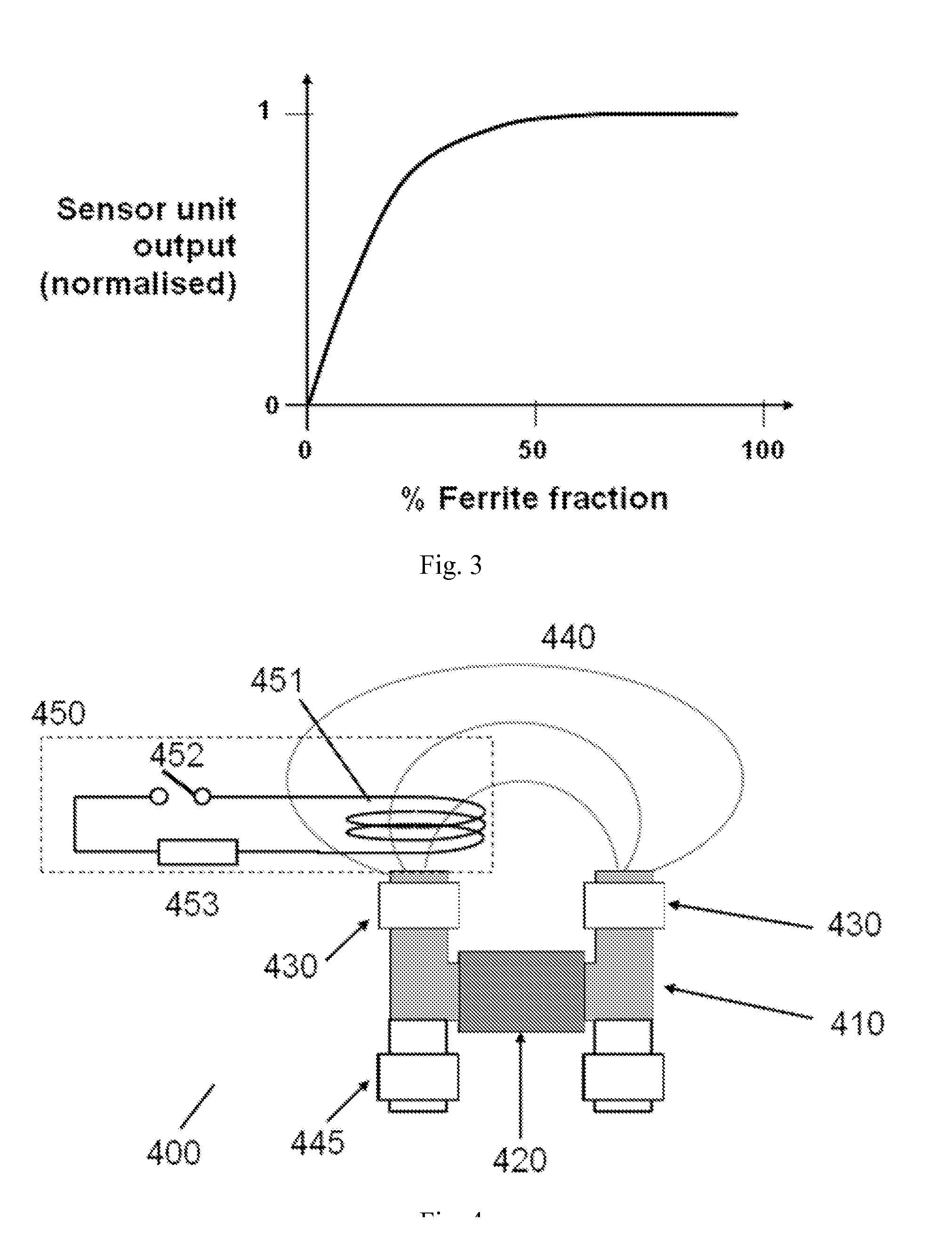
[0053]FIG. 4 illustrates an apparatus 400 according to the invention. The apparatus is an electromagnetic sensor unit 400 for sensing a microstructure of a metal target.

[0054]The sensor unit 400 comprises a magnetic core 410, one or more a magnetic excitation sources 420 and one or more magnetic detectors 430. The magnetic core 410 is configured to apply an interrogating magnetic field 440 generated by the excitation source(s) 420 to a metal target (not shown). The metal core 410 may be U-shaped, as shown in FIG. 4, or may be configured as a different shape, such as H-shaped. The excitation source 420 may be a permanent magnet, an electromagnet or a combination thereof. The magnetic detector 430 is arranged for detecting a magnetic field 440 and may include one or more induction detector coils and / or Hall probe sensors. Other magnetometers are also envisaged. In some embodiments, the sensor unit 400 comprises two magnetic detectors 430, each fitted to a corresponding pole of the mag...
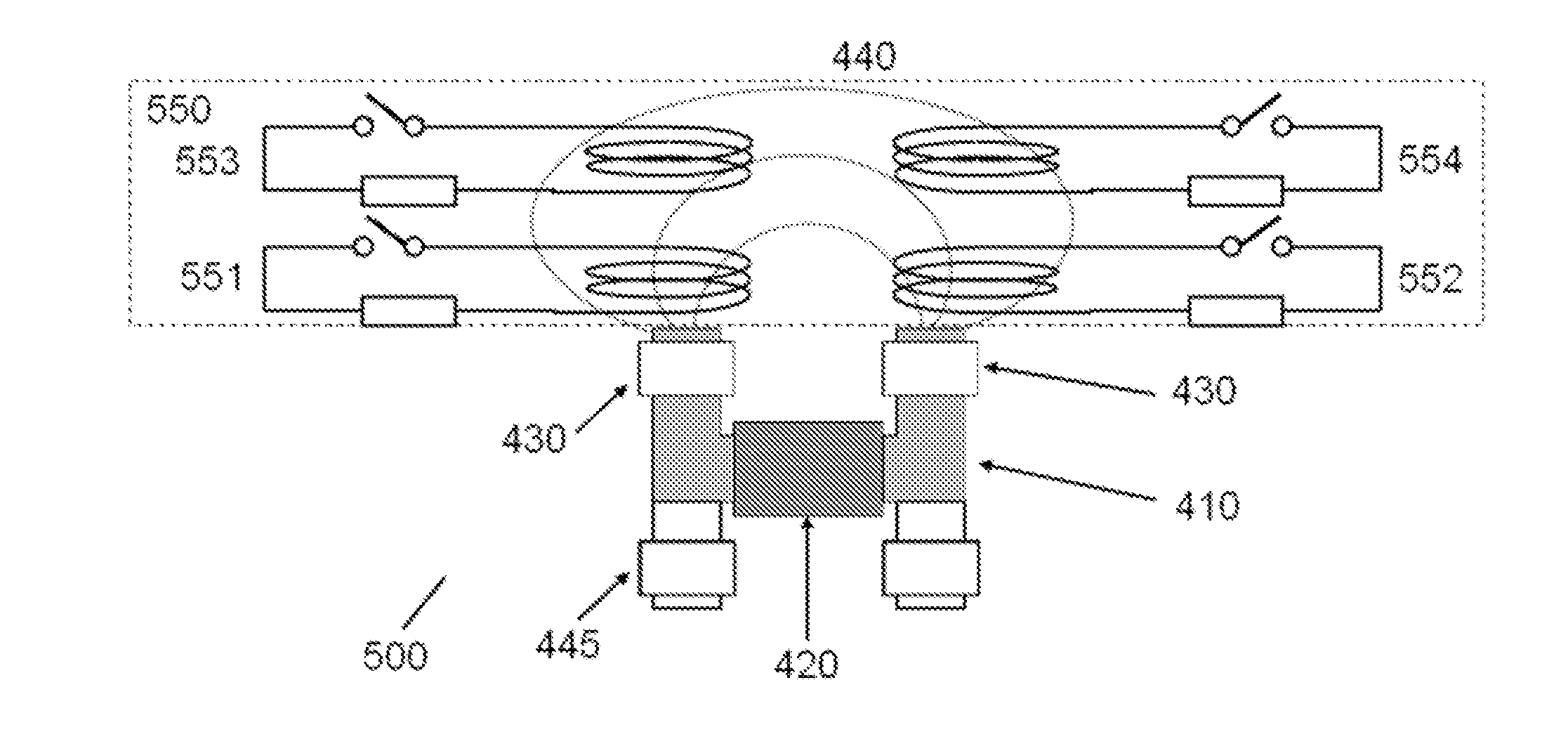
second embodiment

[0060]Each of the calibration circuits 551, 552, 553, 554 may be individually controlled to generate a corresponding magnetic field. Each calibration coil may be configured to operate within a different respective calibration frequency range to calibrate the response of the sensor unit 500 at each frequency range. A first calibration coil 551 may be configured to operate within a first calibration frequency range, which is a relatively low frequency range. The configuration may include providing the first calibration coil 551 with one or relatively few turns. Similarly, the reference impedance associated with the first calibration coil 551 may be relatively low. A fourth calibration coil 554 may be configured to operate within a fourth frequency range, which is a relatively high calibration frequency range. The configuration may include providing the fourth calibration coil 554 with a relatively large number of turns. Second and third calibration coils 552, 553 may be configured to ...


PUM

PropertyMeasurementUnit
Curie temperatureaaaaaaaaaa
tensile strengthsaaaaaaaaaa

Abstract

Embodiments of the present invention provide an electromagnetic sensor (400) for detecting a microstructure of a metal target, comprising: a magnetic device (410, 420) for providing an excitation magnetic field; a magnetometer (430) for detecting a resultant magnetic field induced in a metal target; and a calibration circuit (450, 551, 552, 553, 554) for generating a calibration magnetic field for calibrating the electromagnetic sensor, wherein the calibration reference magnetic field is generated by an electrical current induced in the calibration circuit by the excitation magnetic field.

Description

[0001]Embodiments of the present invention relate to apparatus and methods for monitoring the microstructure of a metal target. In particular, although not exclusively, some embodiments of the present invention relate to apparatus and methods for calibrating electromagnetic sensors. In particular, although not exclusively, some embodiments of the invention relate to monitoring the microstructural formation of a metal target.BACKGROUND[0002]During production processing of metals, such as steel, rolling of the metal is followed by controlled cooling. During the production processing, particularly the cooling process, a microstructure of the metal evolves and results in a final microstructure of the processed metal. The microstructure of the processed metal has an impact on many aspects of the metal's character, such as tensile strength.[0003]Conventional microstructural analysis techniques are destructive and involve removing samples for analysis from, for example, the end of a coil o...

Claims


Application Information

Patent Timeline
Patent Type & Authority Applications(United States)
IPC IPC(8): G01R35/00
CPCG01R35/005C21D8/12C21D11/005C21D2211/00G01N27/80G01R33/028G01R33/1223G01N33/204B21B38/04G01N27/72G01R33/0035G01R33/12B21B37/76G01N33/2045
Inventor PEYTON, ANTHONY JOSEPHYIN, WULIANGDICKINSON, STEPHEN JOHN
Owner UNIV OF MANCHESTER
Why Eureka
Try Eureka