Thermal protector

a technology of thermal protection and protective plate, which is applied in the direction of thermally actuated switches, electric switches, electrical devices, etc., can solve the problems of excessive deterioration of copper alloy spring performance, inability to use beryllium copper springs in such a high temperature range, and restricted use environment of copper alloys. achieve the effect of preventing deterioration of spring performance, reducing the use environment, and precipitating hardening of metal materials

Active Publication Date: 2014-02-20
UCHIYA THERMOSTAT
View PDF7 Cites 15 Cited by
  • Summary
  • Abstract
  • Description
  • Claims
  • Application Information

AI Technical Summary

Benefits of technology

[0007]Accordingly, in view of the above-described problems, an object of the present invention is to provide a thermal protector configured to be capable of preventing deterioration of the spring performance of the movable plate under high temperatures, maintaining a contact pressure at a contact point even under high temperatures, and keeping an internal resistance low to prevent the operating temperature from dropping.
[0010]According to the present invention, the movable plate and the bypass member are joined together at the specified end portions thereof and the assembly part of the movable plate and the bypass member is subjected to heat treatment to induce precipitation-hardening of the metal material of the movable plate. Consequently, hardness of the metal material of the movable plate is increased, thereby preventing deterioration of spring performance even when the thermal protector is heated to high temperatures. As a result, the contact pressure of the contact point can be maintained. Because the bypass member having a high conductivity is joined to the movable plate, the internal resistance of the thermal protector is decreased to suppress generation of Joule heat due to conducted current, thereby preventing the operating temperature of the thermal protector from dropping. By joining together the movable plate and the bypass member prior to the heat treatment for the precipitation hardening of the metal material of the movable plate, resistance welding can be executed easily because the metal material of the movable plate has no strong film and the metal material of the bypass member has excellent morphological stability.

Problems solved by technology

Although as a material of the movable plate of the thermal protector, conventionally, copper alloy, which is representative of low-resistance materials, is usually used, the copper alloy undergoes an excessive deterioration in spring performance if it is placed under high temperatures.
More specifically, a usage environment of the copper alloy is restricted to temperatures up to 230° C. and beryllium copper used for the springs cannot be used in such a high temperature range.
However, the stainless steels have a large specific resistance in common and when each of them is used for the movable plate of the thermal protector through which a large current flows, a large amount of Joule heat is generated when the current flows, so that an operating temperature of the thermal protector drops remarkably.

Method used


Image

  • Thermal protector
  • Thermal protector
  • Thermal protector

Examples


Embodiment Construction

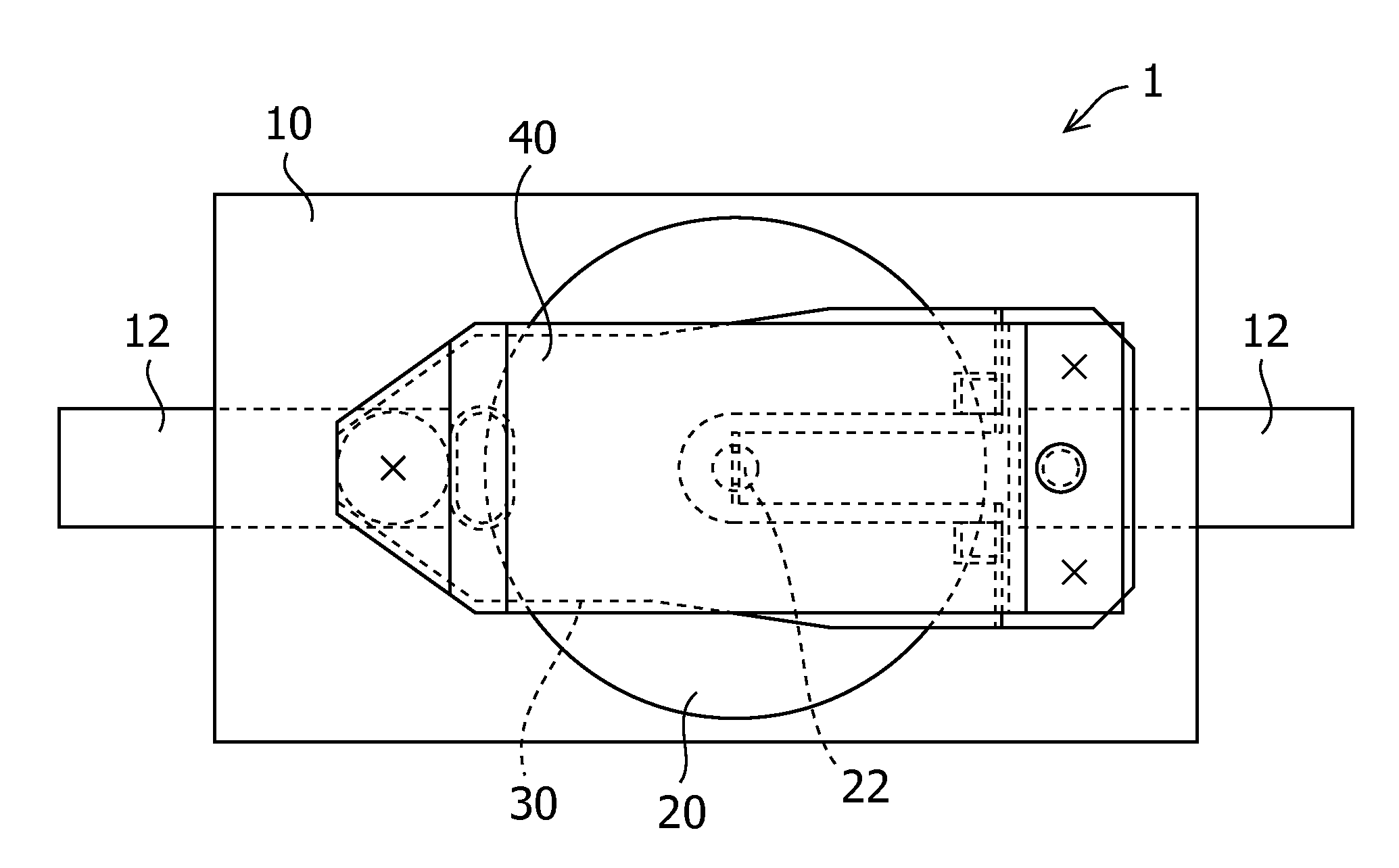
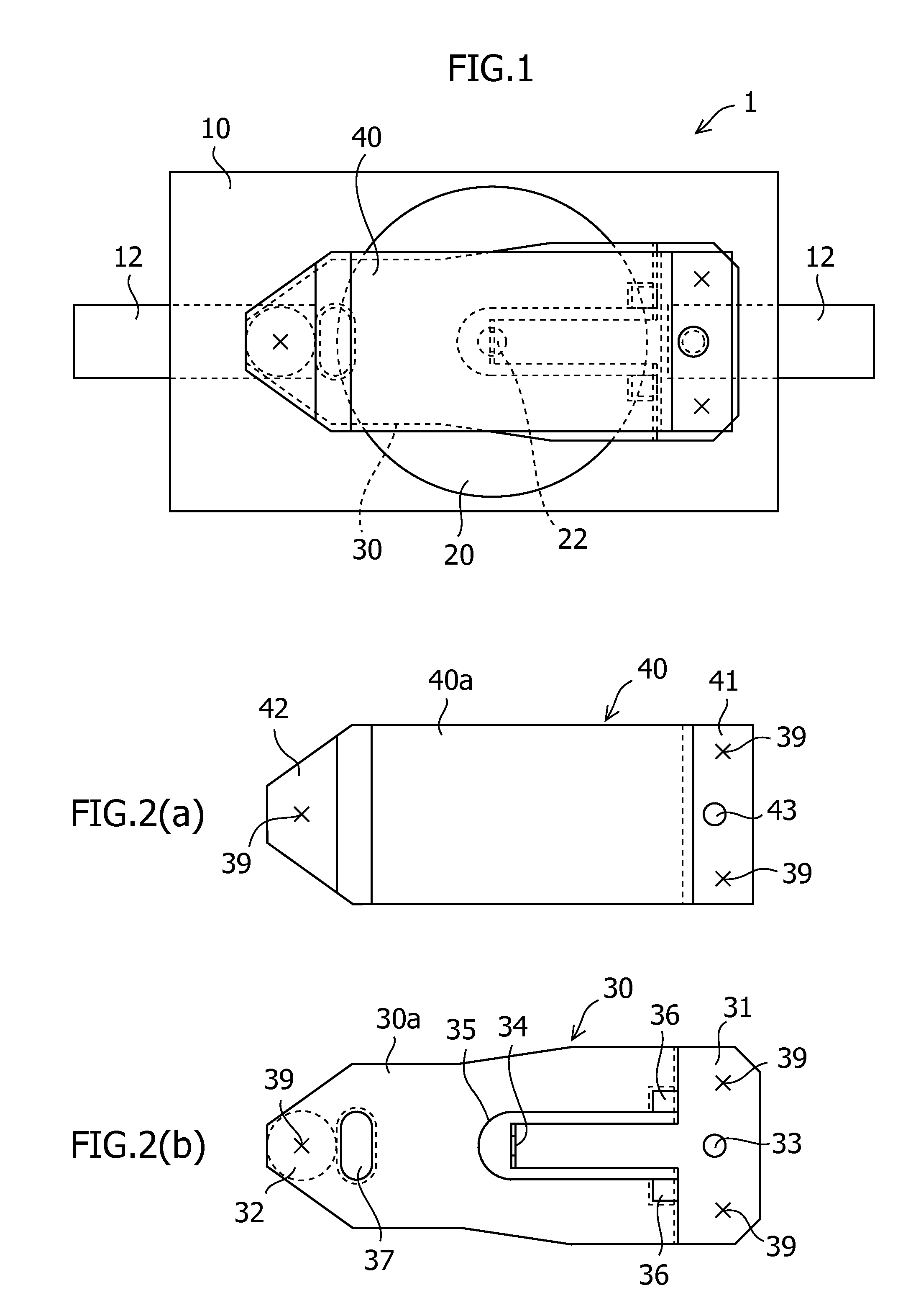
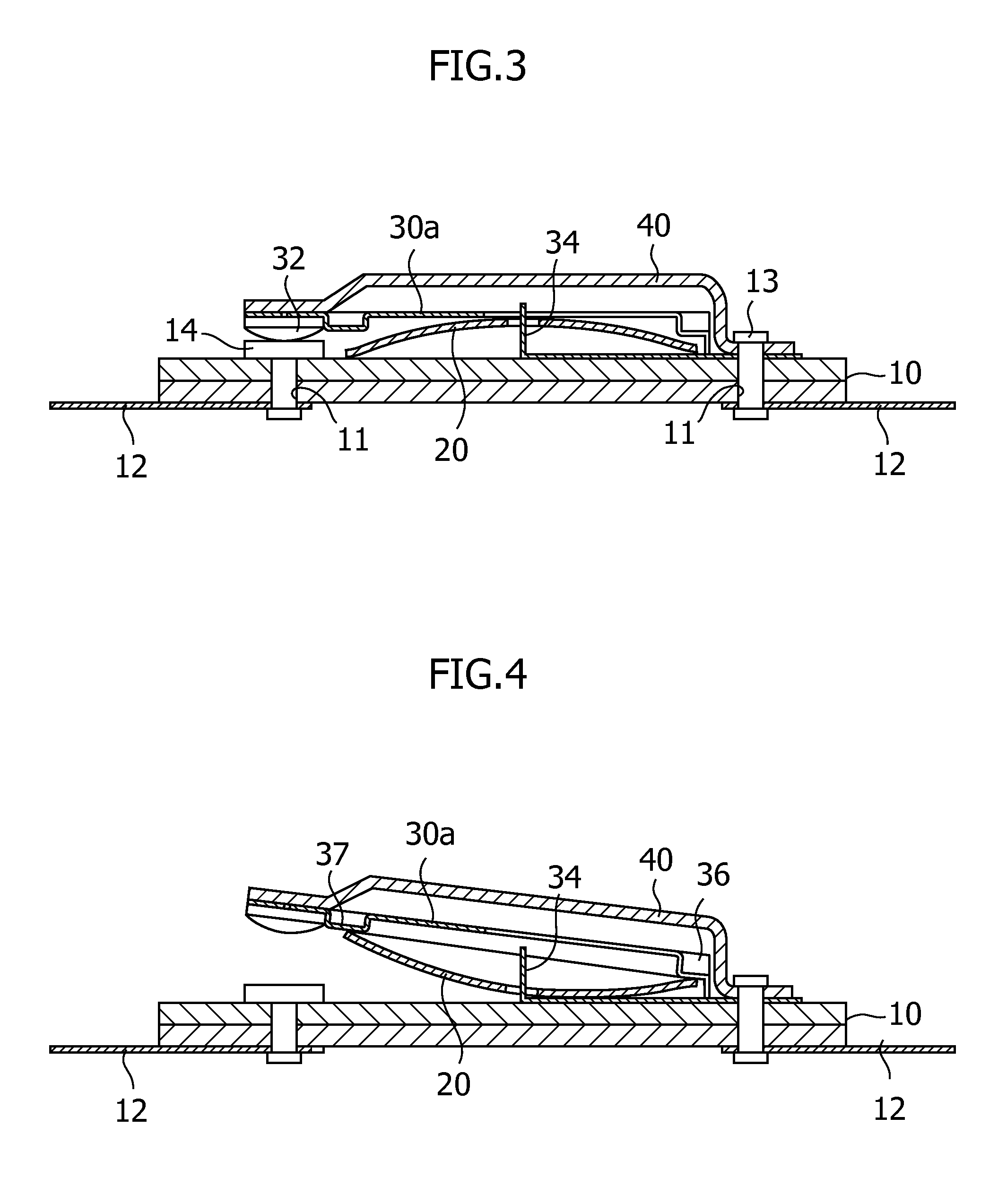
[0016]Hereinafter, an embodiment of the thermal protector according to the present invention will be described with reference to the accompanying drawings. As shown in FIGS. 1 to 4, the thermal protector 1 of this embodiment includes mainly a base 10, a bimetal element 20 which acts as a thermal responsive element, a movable plate 30, and a bypass member 40.

[0017]The base 10 is made of an insulating sheet-like member. The bimetal element 20, the movable plate 30 and the bypass member 40 are mounted on the surface of the base 10, while a lead wire 12 is mounted on a back surface thereof. To connect the movable plate 30 and the bypass member 40 with the lead wire 12 electrically, the base 10 has a through hole 11 which passes through from a front surface to the back surface.

[0018]The bimetal element 20 includes two metal plates, each having a different coefficient of thermal expansion, which are bonded together. This is a snap-acting type thermal responsive element whose curved direct...


PUM


Abstract

A thermal protector for opening and closing an electric circuit, includes: a movable plate having a movable contact point mounted on a one end portion thereof and having a terminal mounted on an opposite end portion thereof; a bypass member joined to the movable plate at the end portions of the movable plate on which the movable contact point and the terminal are mounted; and a thermal responsive element for moving the movable contact point of the movable plate by a snap action thereof to open and close the electric circuit, wherein the bypass member is formed of a first metal material having a higher conductivity than a second metal material of which the movable plate is formed, and the movable plate and the bypass member are joined together and are subjected to heat treatment so that the first metal material of the bypass member is softened while the second metal material of the movable plate is precipitation-hardened.

Description

CROSS-REFERENCE TO RELATED APPLICATION[0001]The disclosure of Japanese Patent Application No. 2010-049443 filed on Mar. 5, 2010, including the specification, claims, drawings, and summary are incorporated herein by reference in its entirety.BACKGROUND OF THE INVENTION[0002]The present invention relates to a thermal protector, more particularly to a thermal protector suitable for a temperature switch which is activated at a high operating temperature such as over 200° C. and has a relatively large current rating.[0003]There has been known a thermal protector which uses a bimetal element as a thermal responsive element to open and close an electric circuit thereof using an inverting action of the element which occurs at a predetermined temperature. As an example of such a thermal protector, Japanese Patent Publication No. 2844026 discloses a thermal protector including a movable plate which has a movable contact point at a distal end thereof and constituted of a spring material; and a...

Claims


Application Information

Patent Timeline
Patent Type & Authority Applications(United States)
IPC IPC(8): H01H37/54
CPCH01H37/54H01H1/26H01H2037/549
Inventor TAKEDA, HIDEAKI
Owner UCHIYA THERMOSTAT
Why Eureka
Try Eureka