Method and Apparatus for Split-Flow-Mixing Liquid Chromatography

a liquid chromatography and flow-mixing technology, applied in the field of high-performance liquid chromatography (hplc), can solve the problems of inability to retain analytes on a reversed phase hplc stationary phase, difficulty becoming more significant, and undesirable situations

a liquid chromatography and flow-mixing technology, applied in the field of high-performance liquid chromatography (hplc), can solve the problems of inability to retain analytes on a reversed phase hplc stationary phase, difficulty becoming more significant, and undesirable situations

US20140061133A1Inactive Publication Date: 2014-03-06THERMO FINNIGAN

Image

  • Method and Apparatus for Split-Flow-Mixing Liquid Chromatography
  • Method and Apparatus for Split-Flow-Mixing Liquid Chromatography
  • Method and Apparatus for Split-Flow-Mixing Liquid Chromatography

Examples


Embodiment Construction

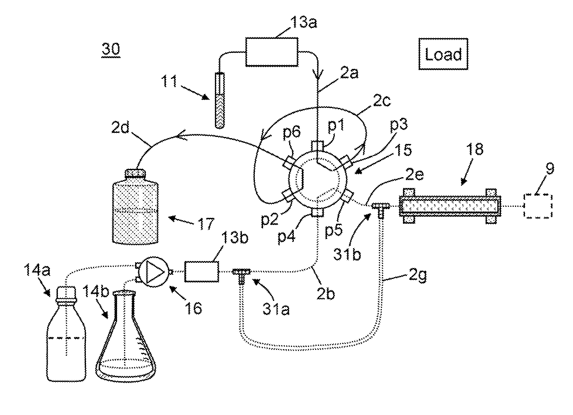
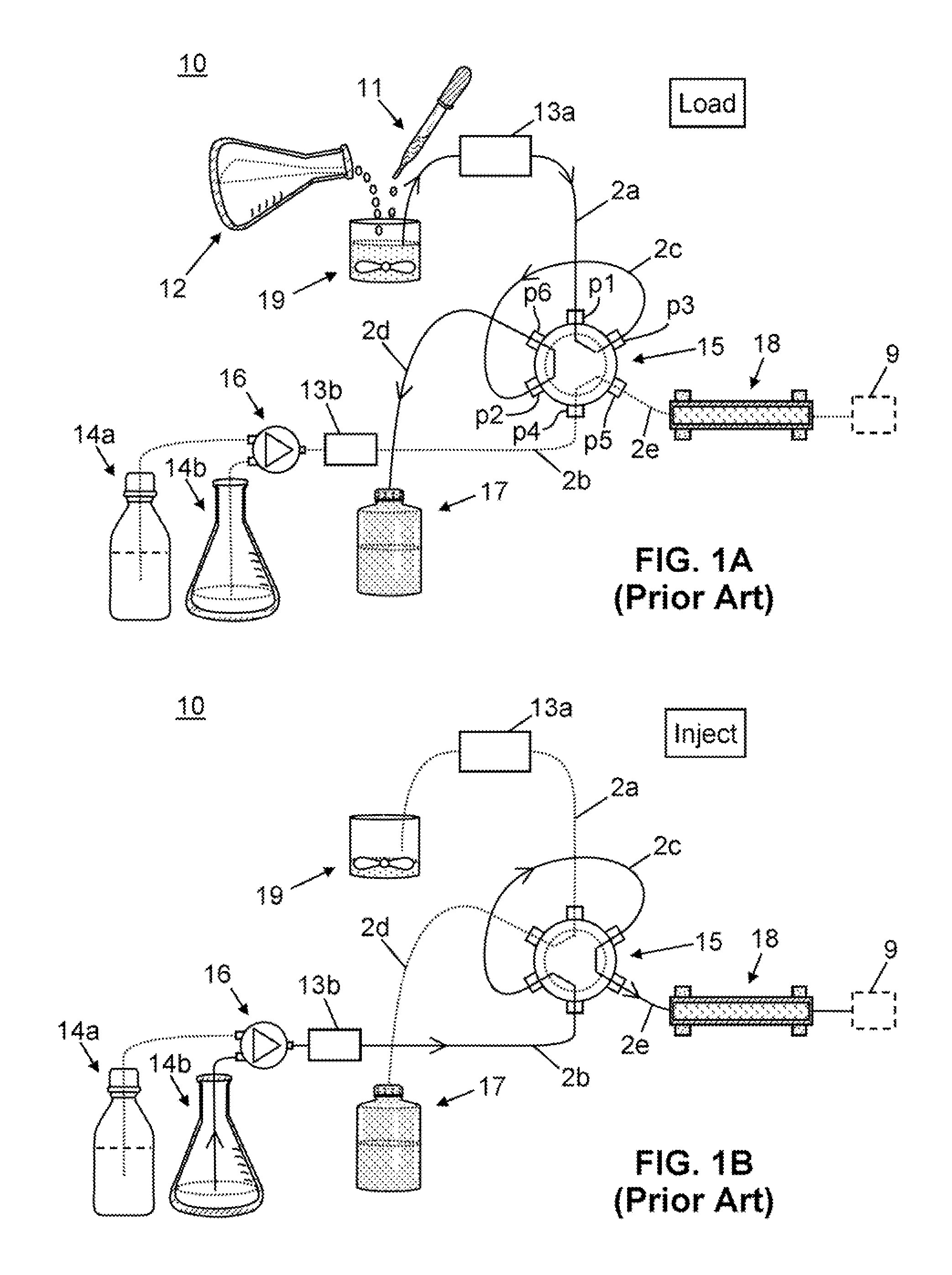
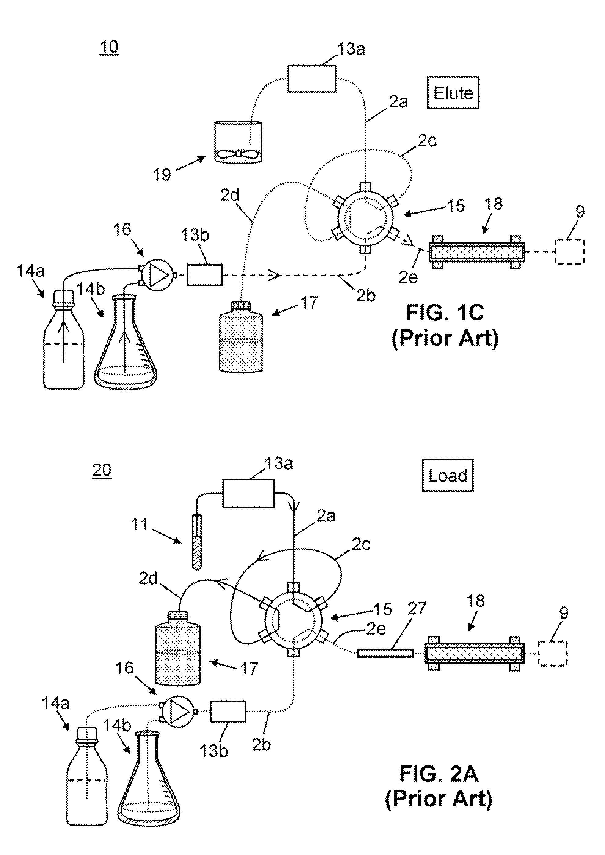
[0039]The following description is presented to enable any person skilled in the art to make and use the invention, and is provided in the context of a particular application and its requirements. Various modifications to the described embodiments will be readily apparent to those skilled in the art and the generic principles herein may be applied to other embodiments. Thus, the present invention is not intended to be limited to the embodiments and examples shown but is to be accorded the widest possible scope in accordance with the features and principles shown and described. The particular features and advantages of the invention will become more apparent with reference to the appended FIGS. 1-12, taken in conjunction with the following description.

[0040]The present invention may be practiced in conjunction with chromatographic methods and systems employing either gradient elution or isocratic elution. Gradient elution, which is the most common type, is illustrated in detail in FI...


PUM


Abstract

A method for chromatographically separating analytes of a liquid sample comprises: (i) providing the sample in a conduit; (ii) providing a solvent for the sample; (iii) causing the solvent to simultaneously flow into the conduit so as to expel the sample from the conduit and flow into and through a second conduit so as to exit said second conduit; (iv) simultaneously providing the expelled sample and the exited solvent to a mixing tee-junction such that the expelled sample and the exited solvent mix thereat; (v) providing the mixture of the expelled sample and the exited solvent to a chromatographic column such that the analytes are transferred to the column and are chromatographically separated therein under the influence of a flow of the solvent, or a different solvent or a mixture of solvents.

Description

FIELD OF THE INVENTION[0001]This invention relates to high performance liquid chromatography (HPLC), and more specifically to techniques for capturing small quantities of analytes injected in organic solvents onto HPLC columns, especially for the purpose of subsequent detection and analysis.BACKGROUND OF THE INVENTION[0002]High-Performance Liquid Chromatography (HPLC) is widely used to separate analytes in liquid samples. Typical HPLC instruments use a high pressure pump for forcing a suitable sample-bearing mobile phase at a constant flow rate through one or more chromatographic separation columns. The sample components are separated within the separation column by one or more mechanisms including sorption, size exclusion, ion exchange or other interactions with the chromatography packing. The sample components are then detected by any conventional detector, e.g., a UV-visible detector, a fluorescence detector, an infrared detector, a mass spectrometer, a Raman detector, or a detec...

Claims


Application Information

Patent Timeline
06 Mar 2014
Publication
US20140061133A1
IPC
B01D15/08; B01D15/18
CPC
G01N30/34; G01N30/20
Inventors
HERMAN, JOSEPH, LEWIS