Variable wavelength interference filter, optical module, electronic apparatus, and method of manufacturing variable wavelength interference filter

a technology of variable wavelength interference and filter, which is applied in the direction of paper/cardboard containers, instruments, transportation and packaging, etc., can solve the problems of deterioration of drive characteristics and optical characteristics of variable wavelength interference filters, affecting the quality of the product, and requiring a lot of cost and time for the package, so as to improve the manufacturing efficiency

Active Publication Date: 2014-03-06
SEIKO EPSON CORP
View PDF7 Cites 9 Cited by
  • Summary
  • Abstract
  • Description
  • Claims
  • Application Information

AI Technical Summary

Benefits of technology

[0036]In this application example, in the state in which the variable wavelength interference filters are arranged in an array, the first penetration section communicating with the first gap is provided to the second substrate, the second penetration section communicating with the second gap is provided to the third substrate, the first sealing groove through which the first gap and the first penetration section communicate with each other is provided to the first substrate, the second sealing groove through which the second gap and the second penetration section communicate with each other is provided to the third substrate, and then the first substrate and the second substrate, and the second substrate and the third substrate are bonded to each other via the bonding layer, respectively. Then, by forming the sealing member in each of the first gap and the second gap via the first penetration section, the second penetration section, the first sealing groove, and the second sealing groove, and then cutting the bonded body into segments corresponding respectively to the variable wavelength interference filters, the variable wavelength interference filters each having the inner spaces sealed can be manufactured. Since the variable wavelength interference filters can be manufactured in a lump as an array, the manufacturing efficiency can be improved.

Problems solved by technology

There is a concern that such a variable wavelength interference filter is deteriorated in drive characteristics and optical characteristics due to an environmental factor such as moisture or foreign matters, and is thus degraded in reliability.
Therefore, in order to ensure the reliability of the variable wavelength interference filter, a lot of cost and time is required for the package, as a separate component, and the assembling of the package.
Further, since the package as a separate component has walls for housing the variable wavelength interference filter and airtightly sealing the periphery of the variable wavelength interference filter, there is a problem that the size of the variable wavelength interference filter including the package increases.

Method used


Image

  • Variable wavelength interference filter, optical module, electronic apparatus, and method of manufacturing variable wavelength interference filter
  • Variable wavelength interference filter, optical module, electronic apparatus, and method of manufacturing variable wavelength interference filter
  • Variable wavelength interference filter, optical module, electronic apparatus, and method of manufacturing variable wavelength interference filter

Examples


first embodiment

Functions and Advantages of First Embodiment

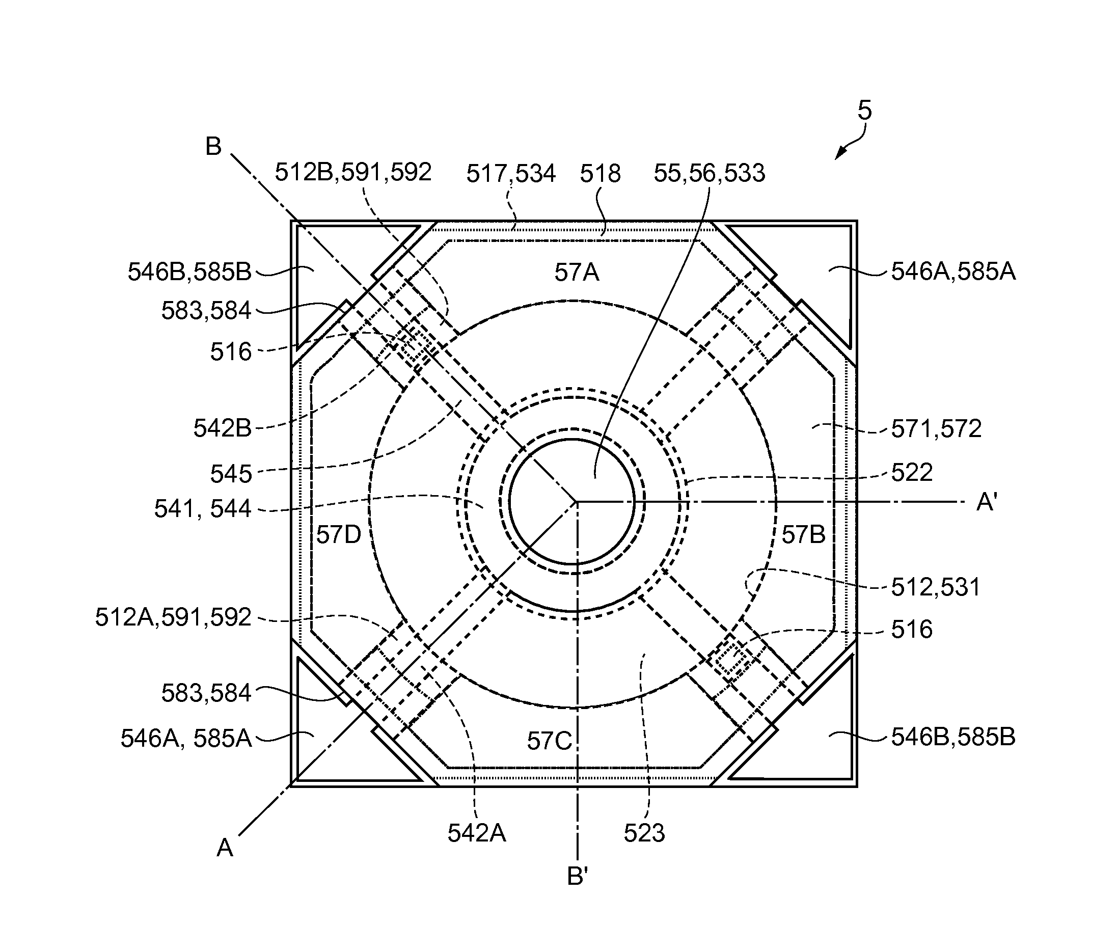
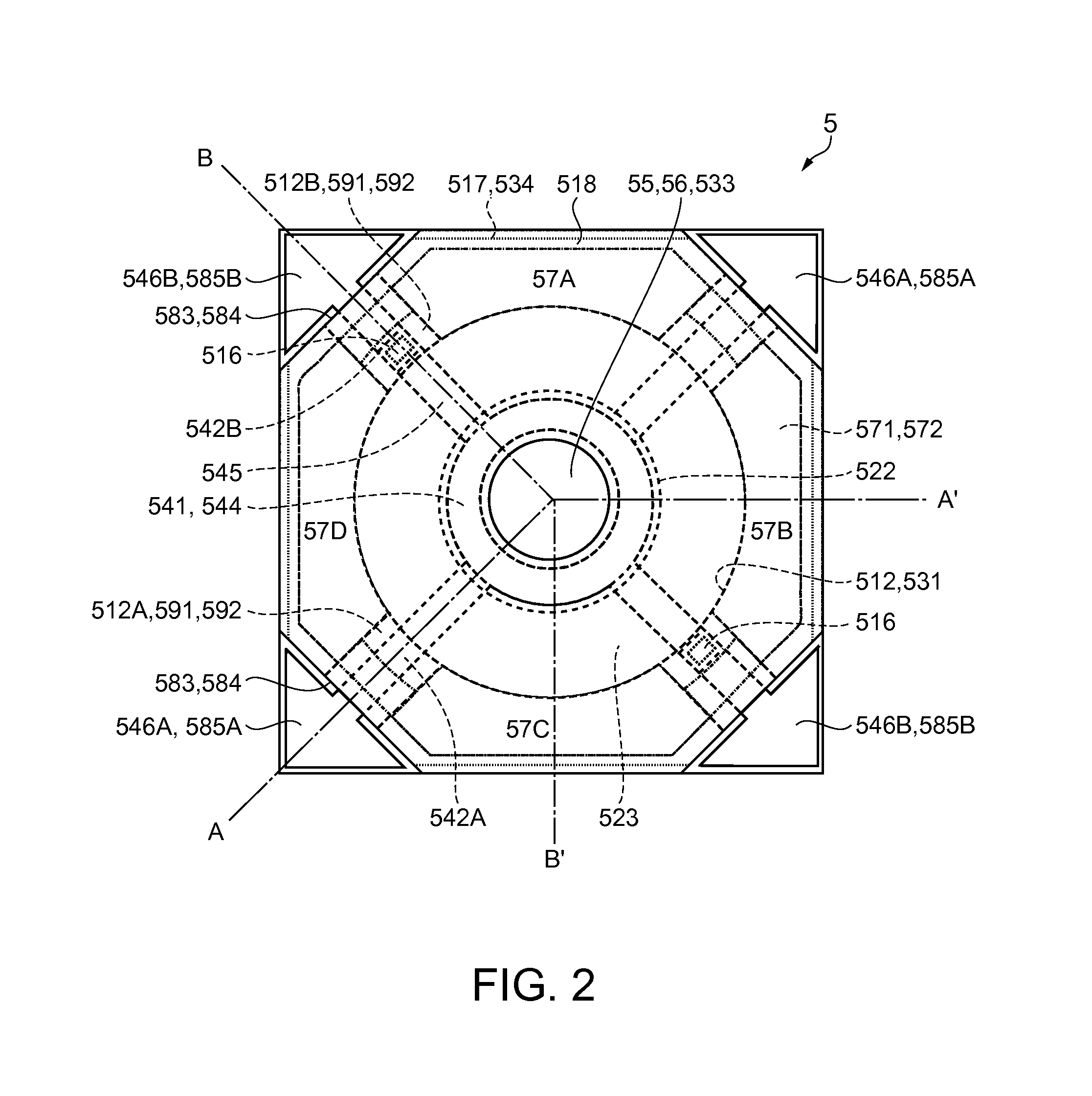
[0114]As described above, in the variable wavelength interference filter 5 according to the first embodiment described above, the first gap 591 and the second gap 592, where the bonding surfaces 513 and 524, 525 and 532 are not bonded to each other, are formed between the bonding surfaces 513, 524, and between the bonding surfaces 525, 532, respectively. Further, the gaps communicate with the first inner space 581 between the first substrate 51 and the second substrate 52 of the variable wavelength interference filter 5, the second inner space 582 between the second substrate 52 and the third substrate 53, and the outside. Therefore, by sealing the first gap 591 and the second gap 592 with the sealing member 518, the first inner space 581 and the second inner space 582 can airtightly be sealed. Thus, since the stationary mirror 55, the movable mirror 56, and the movable section 522 are disposed in the first inner space 581 and the second i...

second embodiment

Functions and Advantages of Second Embodiment

[0125]In the variable wavelength interference filter 5A according to the second embodiment, the following functions and advantages can be obtained.

[0126]Specifically, the through-holes 526, through which the first inner space 581 and the second inner space 582 communicate with each other, are provided to the second substrate 52A. Therefore, when performing the sealing while keeping the first inner space 581 and the second inner space 582 in the reduced-pressure state, the dry-air atmosphere, or the nitrogen atmosphere, the pressure in the first inner space 581 and the pressure in the second inner space 582 can be equalized. Therefore, the fluctuation of the movable mirror 56 due to the difference in pressure between the inner spaces can be suppressed to thereby accurately drive the movable mirror 56.

[0127]Further, in the optical module 10 and the spectroscopic measurement device 1 each using such a variable wavelength interference filter ...


PUM

PropertyMeasurementUnit
thicknessaaaaaaaaaa
depthaaaaaaaaaa
depthaaaaaaaaaa

Abstract

A variable wavelength interference filter includes a first substrate having a stationary mirror, a second substrate bonded to the first substrate and provided with a movable section and a movable mirror fixed to the movable section, and a third substrate bonded to the second substrate on an opposite side to the first substrate, and is provided with a first inner space sandwiched by the first substrate and the second substrate, a first gap, through which the first inner space communicates with the outside, a second inner space sandwiched by the second substrate and the third substrate, and a second gap, through which the second inner space communicates with the outside, and the first gap and the second gap are each sealed by a sealing member.

Description

BACKGROUND[0001]1. Technical Field[0002]The present invention relates to a variable wavelength interference filter for selectively emitting light with a desired target wavelength out of the incident light, an optical module equipped with the variable wavelength interference filter, an electronic apparatus equipped with the optical module, and a method of manufacturing a variable wavelength interference filter.[0003]2. Related Art[0004]In the past, there has been known a spectral filter, which reflects light between a pair of mirrors to transmit light with a specific wavelength while canceling out lights with other wavelengths each other due to interference, to thereby obtain the light with the specific wavelength out of the incident light. Further, as such a spectral filter, there has been known a variable wavelength interference filter, which selectively emits the light to be emitted by controlling the distance between the mirrors (see, e.g., JP-A-62-257032 (Document 1)).[0005]The ...

Claims


Application Information

Patent Timeline
Patent Type & Authority Applications(United States)
IPC IPC(8): G02B5/28G02B26/00
CPCG02B26/001G02B5/28G02B5/284Y10T156/1052Y10T156/10G01J3/26
Inventor HIROKUBO, NOZOMU
Owner SEIKO EPSON CORP
Why Eureka
Try Eureka