Retainer for ball bearing, and ball bearing

a technology of synthetic resin and retainer, which is applied in the direction of shaft assembly, rotary machine parts, mechanical equipment, etc., can solve the problems of retainer deformation, and achieve the effect of reducing the resistance, reducing the torque of the bearing (ball bearing), and eliminating the effect of extra lubricant on the torqu

Inactive Publication Date: 2014-03-06
NTN CORP
View PDF21 Cites 5 Cited by
  • Summary
  • Abstract
  • Description
  • Claims
  • Application Information

AI Technical Summary

Benefits of technology

[0034]In the retainer for a ball bearing according to the present invention, it is possible to reduce the resistance generated at the time of passage of a lubricant through the inside of the pockets, and an amount of oil films to be sheared due to movement of the balls. As a result, reduction in torque of the bearing (ball bearing) using this retainer can be achieved. In addition, extra lubricant between the inner peripheral surface and the balls (steel balls) can be discharged therethrough. As a result, the effect of the extra lubricant on the torque can be eliminated. Further, each of the balls (steel balls) can be stably retained in the pocket central portion. Thus, it is possible to prevent backlash of the balls, and provide a high-quality product. In addition, with use of the two annular members, deformation due to a centrifugal force and drop-off of the ball can be effectively prevented.
[0035]Irrespective of whether the ball non-contact surface is provided on the pocket axial end side or on both sides in the pocket circumferential direction of the ball contact surface, extra lubricant between surfaces opposed to the balls and the balls can be discharged. In this way, the effect of the extra oil on the torque can be stably eliminated.
[0036]With the flange portions provided as described above, it is possible to restrict the inflow of the lubricant into the inside (inside of the bearing) and prevent the outflow of the lubricant from the inside (inside of the bearing) to an outside of the bearing. Thus, the lubricant can be stably maintained, and effective reduction in torque can be achieved.
[0037]When the back surface located on the opposite side to each of the opposed surfaces that are snap-fitted to each other for coupling the two annular members to each other with the coupling portions provided at both the end portions in the circumferential direction of each of the pockets is formed into a flat shape over the entire periphery thereof, thinned portions need not be provided unlike conventional retainers. Thus, stirring resistance of the lubricant is not increased during rotation. As a result, torque (heat) to be generated between the retainer and the balls can be easily reduced.
[0038]As a material for the retainer, there may be used a polyamide resin excellent in tensile elongation, tensile strength, shock resistance, abrasion resistance, lubricity, and the like. Accordingly, it is possible to provide a high-quality retainer.
[0039]According to the ball bearing of the present invention, deformation of the retainer due to high-speed rotation can be suppressed, and reduction in torque can be achieved through the restriction on an amount of the inflow of a lubricant and the reduction of the stirring resistance. Thus, when this bearing is used in an automobile, fuel efficiency becomes higher, and hence environmentally friendly driving can be performed. In other words, an automotive ball bearing suited to high rotation bearings used in electric vehicles and hybrid vehicles can be provided. In particular, this ball bearing is optimum to automotive transmissions.

Problems solved by technology

As a result, there arise problems such as deformations of a retainer due to a lack of lubrication, torque (heat generation), and to a centrifugal force.

Method used


Image

  • Retainer for ball bearing, and ball bearing
  • Retainer for ball bearing, and ball bearing
  • Retainer for ball bearing, and ball bearing

Examples


Embodiment Construction

[0053]In the following, description is made of embodiments of the present invention with reference to the drawings.

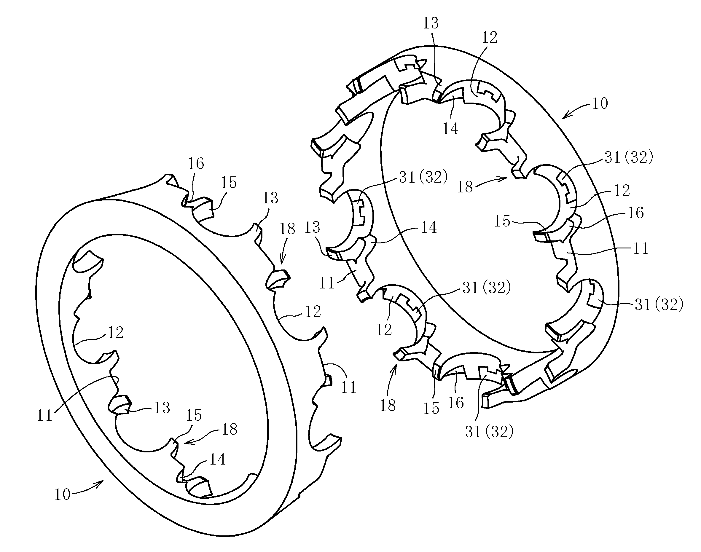
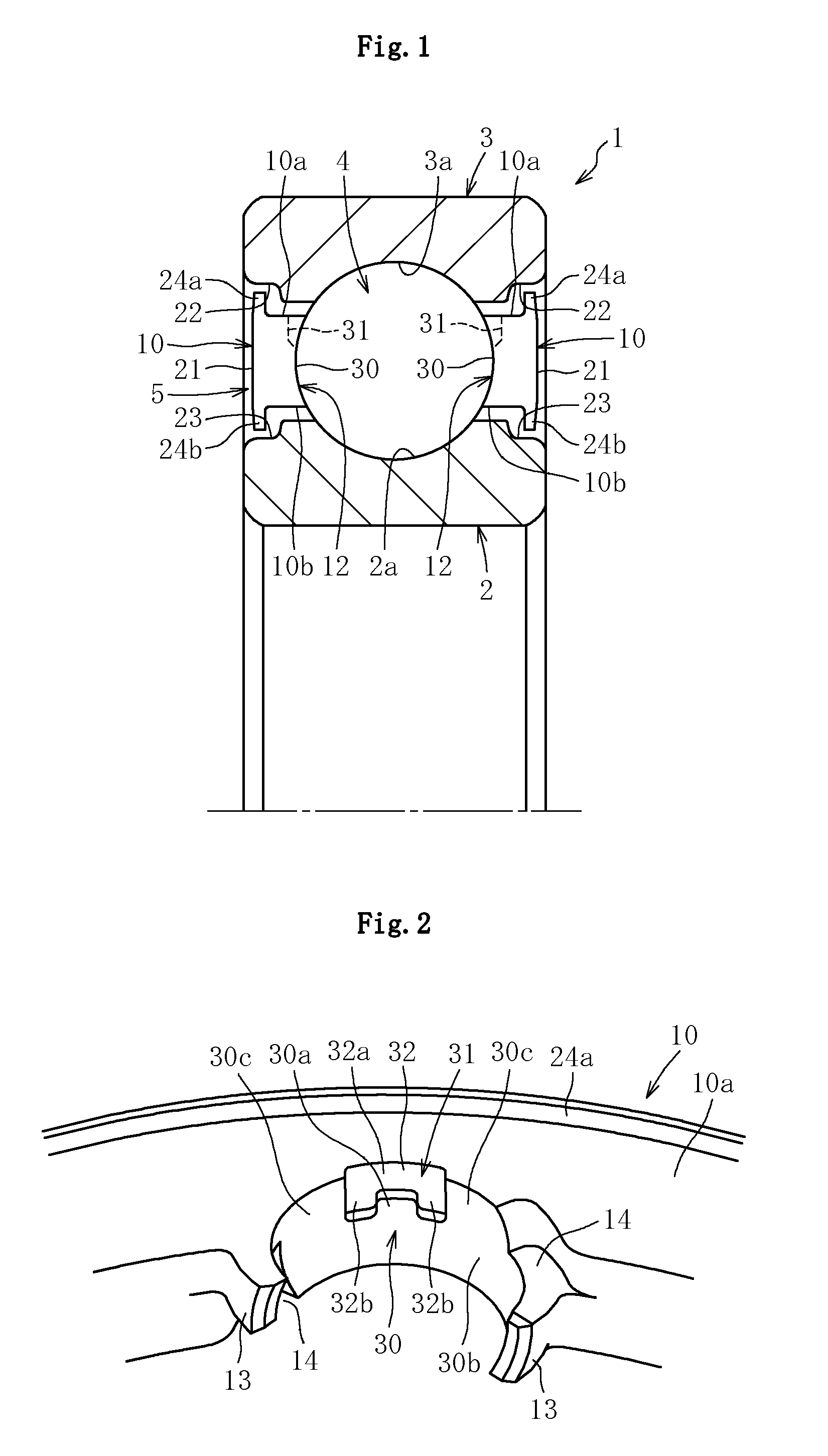
[0054]A ball bearing 1 according to this embodiment comprises, as a main part, an inner race 2 having a radially outer surface formed as an inner raceway surface 2a, an outer race 3 arranged on an outer side with respect to the inner race 2 and having a radially inner surface formed as an outer raceway surface 3a, a plurality of balls 4 interposed in a freely rollable manner between the inner raceway surface 2a of the inner race 2 and the outer raceway surface 3a of the outer race 3, and a retainer 5 arranged between the inner race 2 and the outer race 3 so as to equiangularly retain the balls 4. Any one of the outer race 3 and the inner race 2 is mounted to a fixed part such as a housing, and another is mounted to a rotary part such as a rotary shaft.

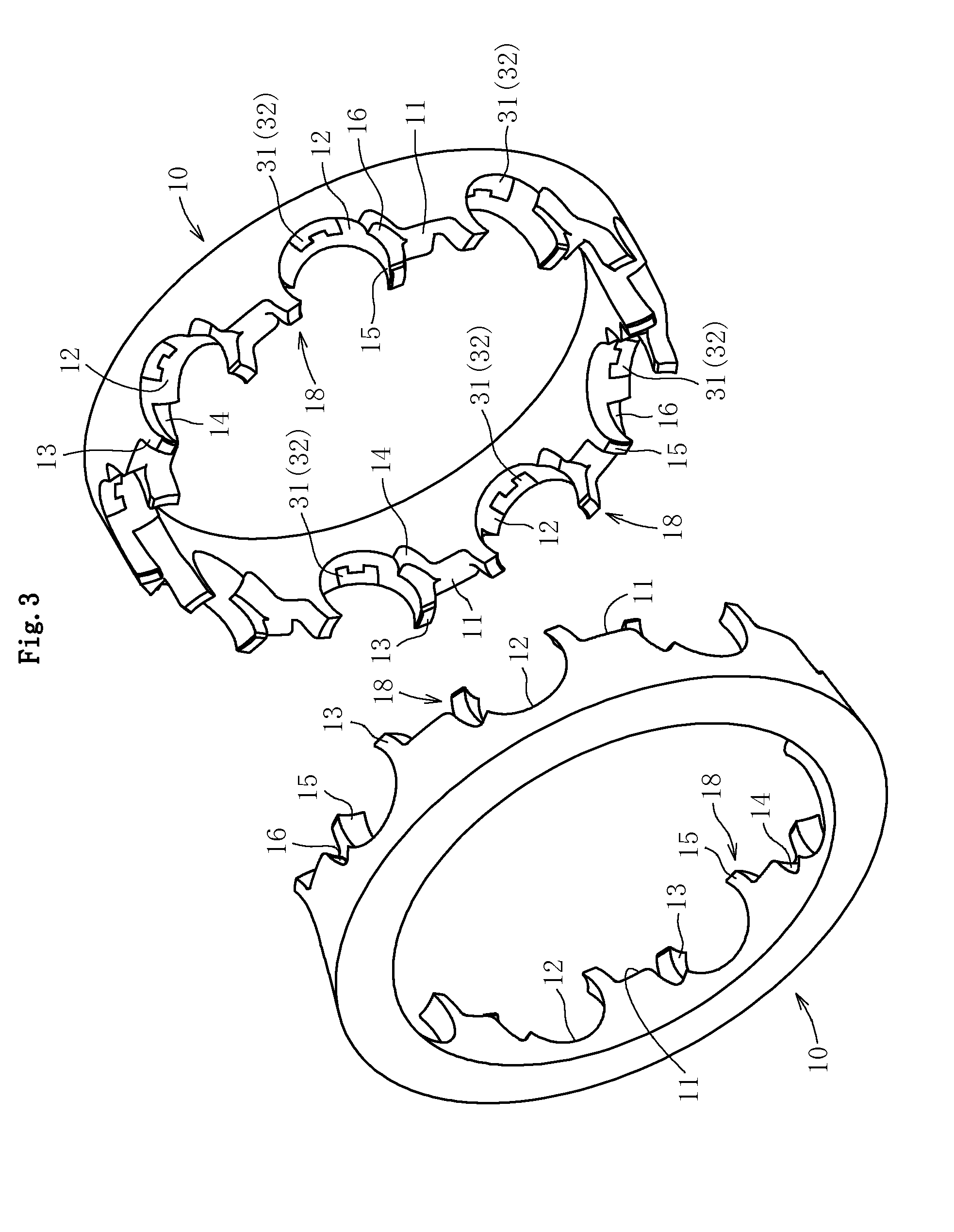
[0055]As illustrated in FIG. 3, the retainer 5 comprises two annular members 10 facing each other in an axial direction ...


PUM

PropertyMeasurementUnit
inclination angleaaaaaaaaaa
inclination anglesaaaaaaaaaa

Abstract

A retainer for a ball bearing includes two annular members that face each other in an axial direction thereof. The two annular members include opposed surfaces each having hemispherical pockets that are formed at positions in a circumferential direction of each of the two annular members and configured to receive balls. The opposed surfaces are snap-fitted to each other to couple together the two annular members. The hemispherical pockets each have an inner peripheral surface provided with ball contact and ball non-contact surfaces. The ball contact surface is formed at a central portion in a pocket circumferential direction and at least at a central portion in a pocket axial direction of the inner peripheral surface. The ball non-contact surface includes a recess recessed to an opposite side to a corresponding ball across the ball contact surface and is opened in at least one of pocket axial ends.

Description

TECHNICAL FIELD[0001]The present invention relates to a synthetic resin retainer for a ball bearing, which is configured to retain balls in a freely rollable manner, and to a ball bearing having the retainer interposed between an outer race and an inner race.BACKGROUND ART[0002]Various sealed ball bearings, such as a deep groove ball bearing and an angular contact ball bearing, are widely used, for example, for a gear support shaft of a transmission of a vehicle including an engine.[0003]A ball bearing of this type includes an inner race having a radially outer surface formed as an inner raceway surface, an outer race arranged on an outer side with respect to the inner race and having a radially inner surface formed as an outer raceway surface, and a plurality of balls interposed in a freely rollable manner between the inner raceway surface of the inner race and the outer raceway surface of the outer race. A retainer is arranged between the inner race and the outer race so as to equ...

Claims


Application Information

Patent Timeline
Patent Type & Authority Applications(United States)
IPC IPC(8): F16C33/38F16C33/78
CPCF16C33/7823F16C33/3875F16C2208/36F16C2208/60F16C2208/52F16C2326/01F16C33/7893F16C2361/61F16C2226/74F16C33/6651F16C33/3806F16C19/06F16C33/3887F16C33/3862
Inventor FUKAMA, SHOHEIKATAYAMA, YASUYUKIOKADA, TAKAHIROSASAKI, KATSUAKI
Owner NTN CORP
Why Eureka
Try Eureka