Sulfur degasser apparatus and method

a technology of sulfur degasser and degasser body, which is applied in the direction of machines/engines, combustion air/fuel air treatment, and combustion gas purification/modification. it can solve the problems of promote vigorous agitation, and achieve rapid removal of hydrogen sulfide. , the effect of large surface area

Active Publication Date: 2014-03-06
IPCO US LLC
View PDF4 Cites 11 Cited by
  • Summary
  • Abstract
  • Description
  • Claims
  • Application Information

AI Technical Summary

Benefits of technology

[0021]According to one aspect of one or more embodiments of the present invention, the invention consists of a compact, portable, inexpensive apparatus and process that produces a high-quality product with less than 10 ppmw of H2S. Rapid degassing is achieved using a novel sparging system. In one embodiment, the sparging system uses a perforated plate and compartments to produce a high concentration of gas bubbles in the sulfur liquid. The high concentration of gas bubbles rising through the sulfur results in a large surface area and promotes vigorous agitation that results in the rapid removal of hydrogen sulfide. Use of a catalyst such as n amine or a mixture of amines results in the rapid removal of hydrogen polysulfide from the liquid sulfur.

Problems solved by technology

The high concentration of gas bubbles rising through the sulfur results in a large surface area and promotes vigorous agitation that results in the rapid removal of hydrogen sulfide.

Method used


Image

  • Sulfur degasser apparatus and method
  • Sulfur degasser apparatus and method
  • Sulfur degasser apparatus and method

Examples


Embodiment Construction

[0027]Specific embodiments of the present invention will now be described in detail with reference to the accompanying figures. Like elements in the various figures are denoted by like reference numerals for consistency. Further, in the following detailed description of embodiments of the present invention, numerous specific details are set forth in order to provide a more thorough understanding of the present invention. In other instances, well-known features have not been described in detail to avoid obscuring the description of embodiments of the present invention.

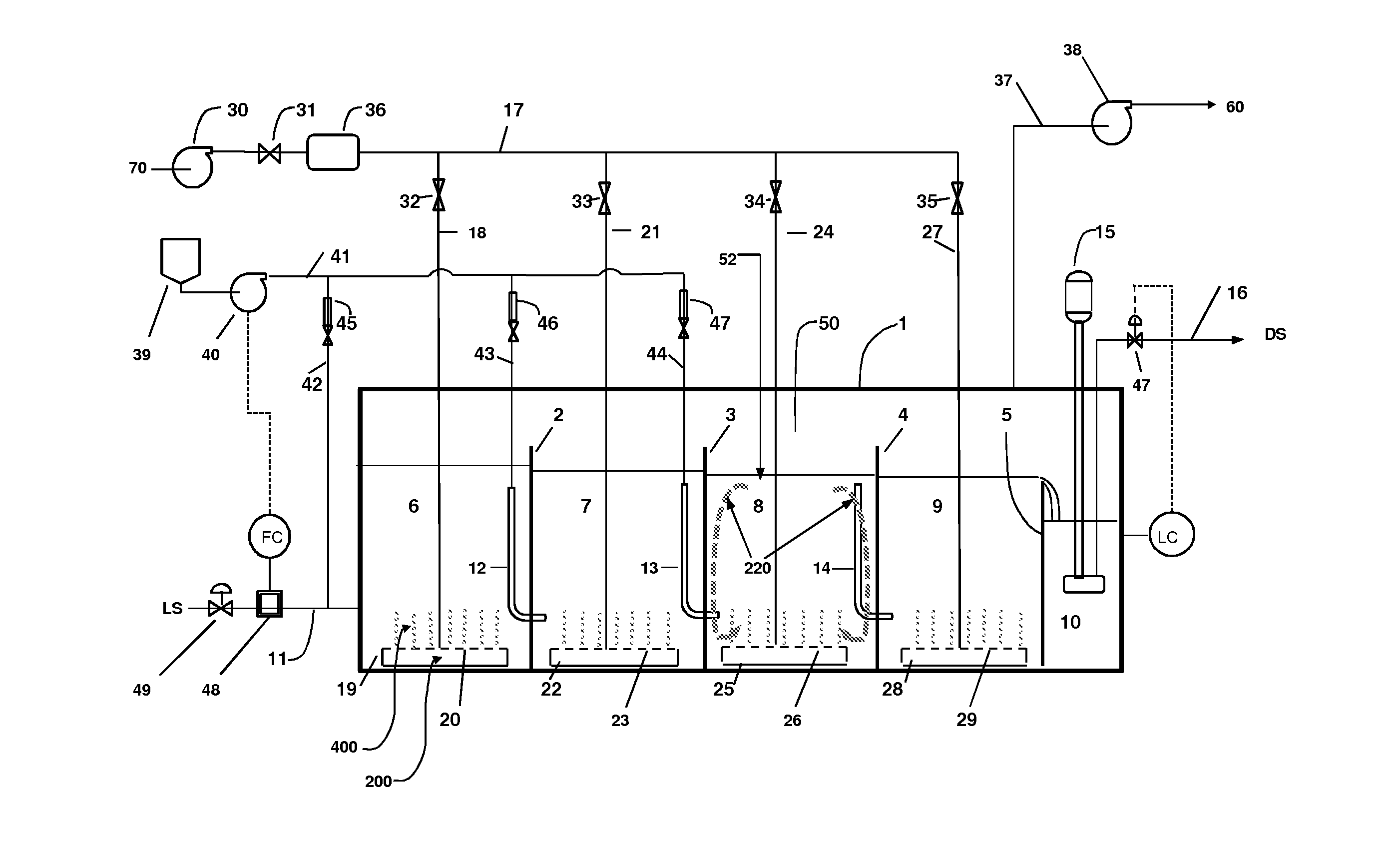
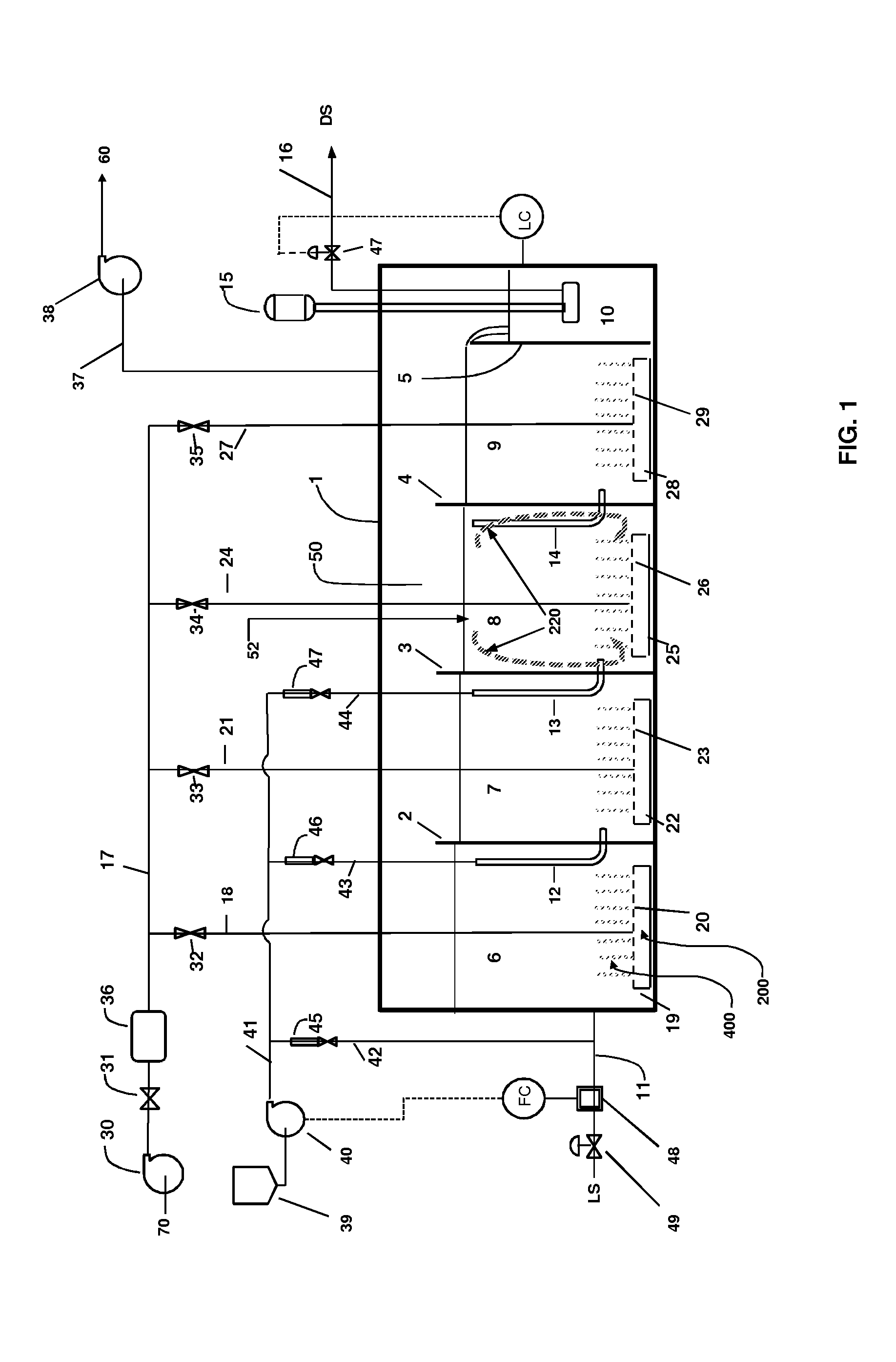
[0028]FIG. 1 shows a cutaway elevation view of a degasser apparatus in accordance with one or more embodiments of the present invention. The degasser apparatus consists of a vessel 1. The shape of the vessel 1 shown in the figure is a box like shape. One skilled in the art will recognize that the shape of the vessel does not have to be a box shaped, rather what is important is that the vessel is sized to suit the produc...


PUM

PropertyMeasurementUnit
diameteraaaaaaaaaa
temperatureaaaaaaaaaa
heightaaaaaaaaaa

Abstract

A novel system and method for degassing H2S and H2Sx from liquid sulfur (sulphur) is disclosed. The system includes a degassing vessel with a plurality of cells. The cells include a sparging gas mat with a perforated surface at the bottom of the cell to allow the release of air bubbles (or sparging gas) into the cells. A catalyst may be used during the process. As a result, hydrogen sulfide and hydrogen polysulfide are efficiently and effectively removed from the liquid sulfur.

Description

CROSS-REFERENCE TO RELATED APPLICATIONS[0001]N / A.STATEMENT REGARDING FEDERALLY SPONSORED RESEARCH OR DEVELOPMENT[0002]N / A.REFERENCE TO MICROFICHE APPENDIX[0003]N / A.BACKGROUND OF INVENTION[0004]1. Field of Invention[0005]The present invention relates to an improved process to remove hydrogen sulfide and hydrogen polysulfide from liquid sulfur (sulphur). Hydrogen sulfide is removed by mass transfer to air bubbles generated by passing air through a perforated plate. A volatile catalyst is used to rapidly decompose hydrogen polysulfide to hydrogen sulfide.[0006]2. Description of the Related Art[0007]The Claus process is extensively used to produce liquid sulfur from sour oil and gas or other gaseous hydrogen sulfide. It is known in the industry that produced sulfur contains two hydrogen sulfide species, namely, physically dissolved hydrogen sulfide, H2S, and hydrogen polysulfide, H2Sx, which is the reaction product of dissolved H2S with liquid sulfur. Liquid sulfur produced in processin...

Claims


Application Information

Patent Timeline
Patent Type & Authority Applications(United States)
IPC IPC(8): B01D19/00B01F3/04C01B17/027
CPCC01B17/0232B01D11/04B01D2011/007
Inventor METHERAL, CASEY J.LANG, LESLIE L.IRANI, JAMSHEED P.WOHLERS, CODY J.DE PAOLI, SERGIO A.
Owner IPCO US LLC
Why Eureka
Try Eureka