Heat exchanger arrangement and air conditioning system of a motor vehicle

a technology of heat exchanger and air conditioner system, which is applied in the direction of indirect heat exchangers, domestic cooling devices, lighting and heating devices, etc., can solve the problems of internal combustion engines that are subjected to start-stop operation at low ambient temperature, the coolant temperature is not sufficiently high, and the effect of increasing the efficiency of the air conditioning system

Active Publication Date: 2014-03-20
HANON SYST
View PDF13 Cites 64 Cited by
  • Summary
  • Abstract
  • Description
  • Claims
  • Application Information

AI Technical Summary

Benefits of technology

[0064]To summarize, the invention-specific solution exhibits various advantages: an efficient air conditioning system for simultaneous demoisturizing and heating; rapid provision of warm air at a low ambient temperature and cold engine coolant water in motor vehicles with an internal combustion engine; minimum complexity in the refrigerant circuit, i.e., in essence doing without switchover valves and minimization of the number of expansion valves, heat exchangers, and refrigerant lines; heating of the air to be fed to the passenger compartment in heat-pump mode or of the air to be diverted to the environment in cooling-unit operation to as high a temperature as possible, which is higher than the condensation temperature of the refrigerant in the refrigerant circuit; making heating power available at a lower maximum pressure level in comparison with traditional heating systems and thus increasing efficiency of the air conditioning system, especially when operated in the heat-pump mode; as well as reduction of costs, since a condenser with a suitable air guide in the compact air conditioner in comparison to a traditional system replaces the condenser in the refrigerant circuit used in the cooling unit mode and the heating warmth exchanger in the engine cooling circuit.

Problems solved by technology

As a consequence of this, the internal combustion engine is run for a longer time at low temperature, which has a negative effect on exhaust emissions and fuel consumption.
Due to the internal combustion engine operating intermittently in hybrid vehicles, during longer trips the coolant temperature does not become sufficiently high.
As a consequence, the internal combustion engine is subjected to start-stop operation at low ambient temperature.
However, the configuration of the refrigerant circuit with switchover valves results in great complexity, which in turn leads to high costs and high technical expense.
With the air conditioners controlled on the air side, however, no operation is possible in the reheating mode, also designated as Reheat.
However, condensers designed for heat-pump operation exhibit less transmission power than condensers designed for heating-unit operation.
If the heat exchanger is run both in the cooling-unit operation and in heat-pump operation as a condenser, arrangement of the condenser in the cooling module of the motor vehicle does not make sense.
Due to the large structural shape of condensers for the cooling unit operation as known in prior art, i.e., with a large flow cross section on the air side, it is almost impossible to place the condenser in an area in the vehicle other than the cooling module.
On the other hand, with one designed in the structural form of a condenser configured for heat-pump operation, the required power for cooling unit operation is not transferable.
In addition, the mass air flow cannot be heated to, or at all above, the condensation temperature of the refrigerant.

Method used


Image

  • Heat exchanger arrangement and air conditioning system of a motor vehicle
  • Heat exchanger arrangement and air conditioning system of a motor vehicle
  • Heat exchanger arrangement and air conditioning system of a motor vehicle

Examples


Embodiment Construction

[0072]The following detailed description and appended drawings describe and illustrate various exemplary embodiments of the invention. The description and drawings serve to enable one skilled in the art to make and use the invention, and are not intended to limit the scope of the invention in any manner.

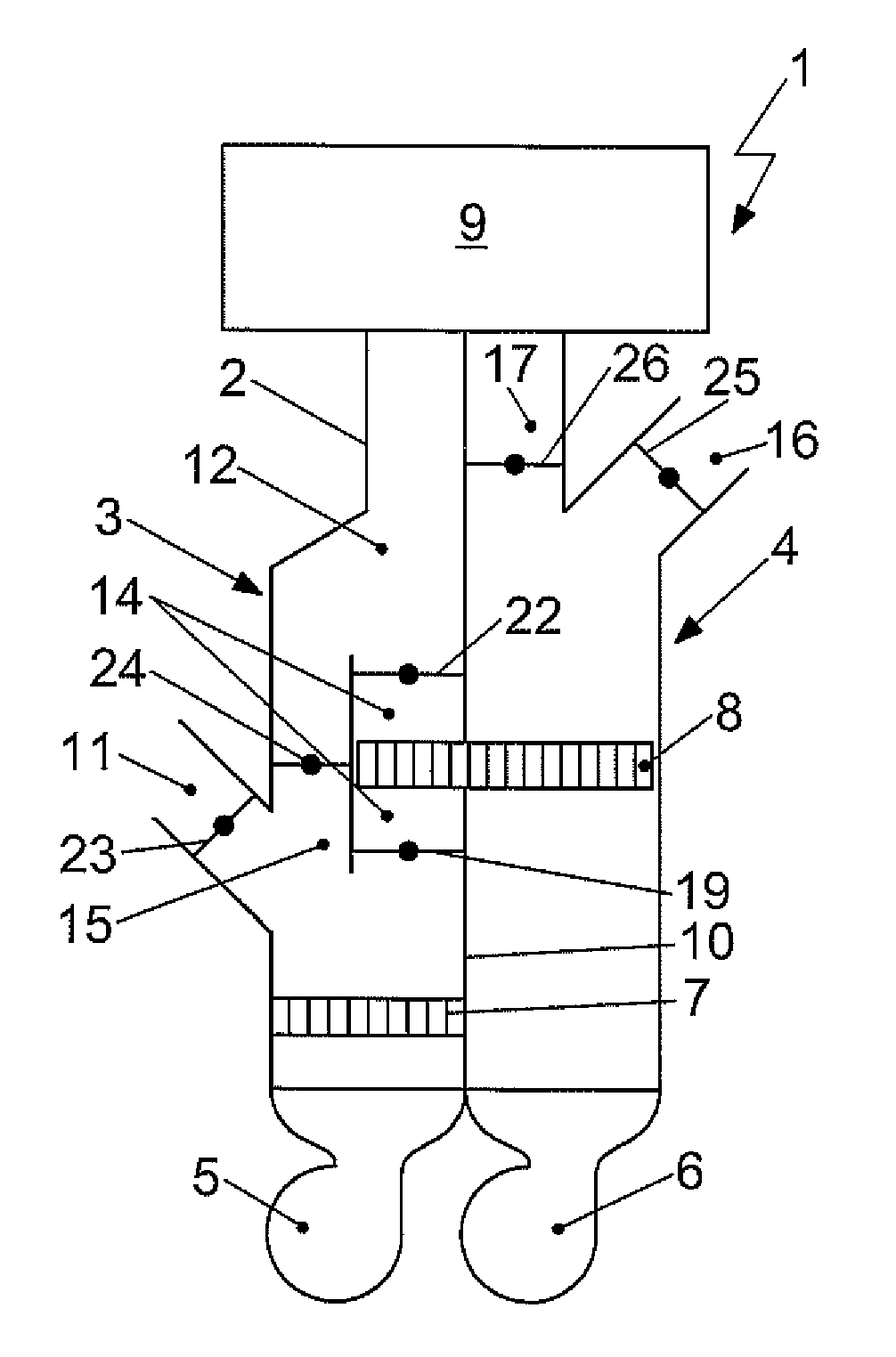
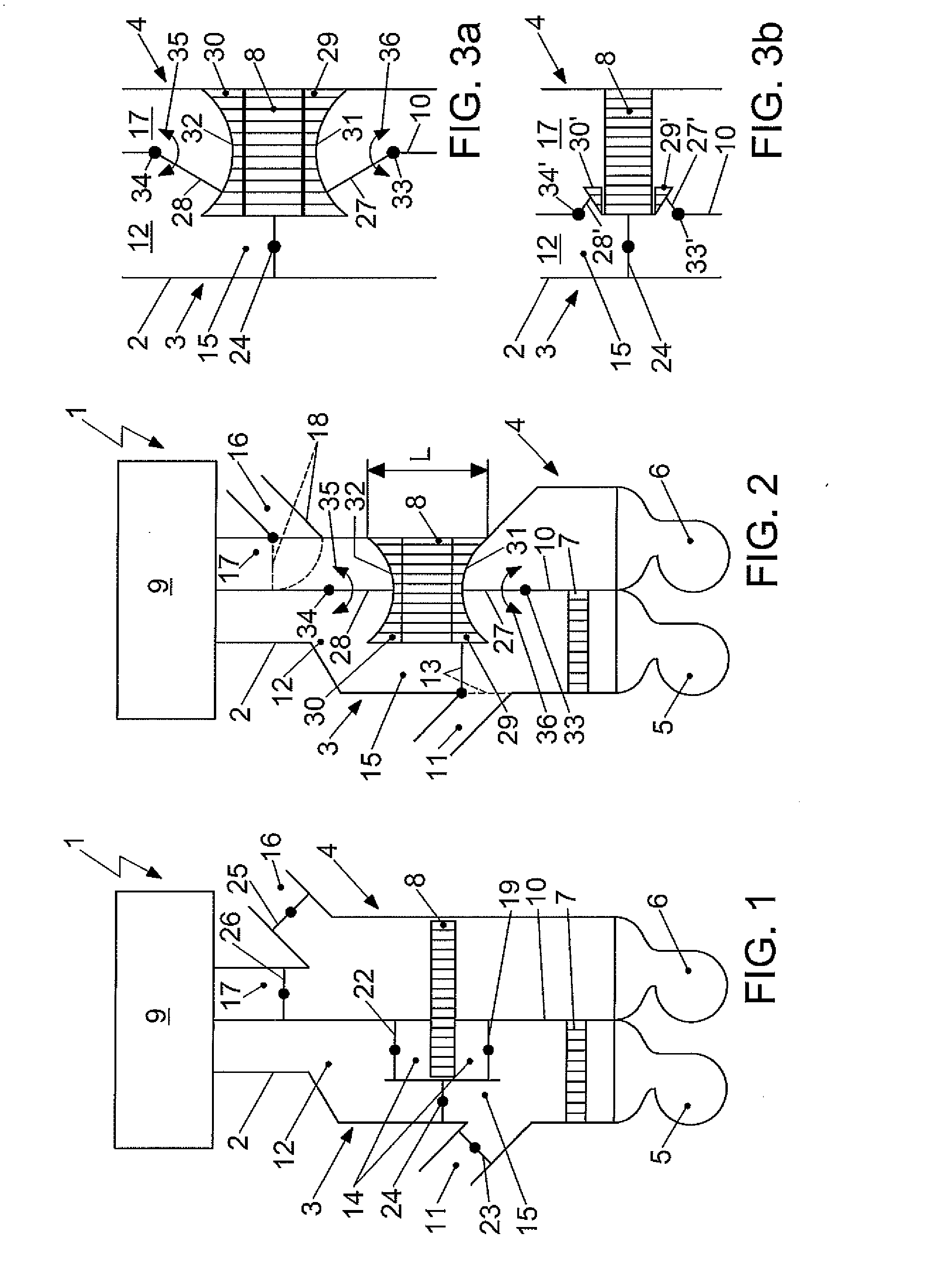
[0073]FIG. 1 shows an air conditioning system 1 with a housing 2, exhibiting a first flow channel 3 and a second flow channel 4, wherein a blower 5, 6 is assigned to each flow channel 3, 4 and is able to be impinged on by fresh air from the ambient environment, recirculated air from the passenger compartment 9, or a mixture of the two.

[0074]A vaporizer 7 is placed in the first flow channel 3, and a condenser 8 is placed in the second flow channel 4, with both configured as components of a refrigerant circuit of the air conditioning system 1 and as air-impinged heat exchangers. The vaporizer 7 admits the entire flow cross section of the flow channel 3. The condenser 8 is situated to o...


PUM


Abstract

The invention relates to a heat exchanger arrangement for heating of air, with a heat exchanger (8) which is integrated into a refrigerant circuit (60), configured to be able to have refrigerant flow through it and able to be impinged on by air. The heat is transferred from the refrigerant to the air. The heat exchanger (8) exhibits two components (8a, 8b) configured to be segregated from each other. The first component (8a) is configured with a condensation surface and a heat-removal surface. The second component (8b) exhibits a supercooling surface. Between the components (8a, 8b) on the refrigerant side, a refrigerant phase separation element is placed. The heat exchanger is configured as a tubular heat exchanger with tubes situated in rows, wherein the first component (8a) is configured with at least two rows and the second component (8b) with at least one row.

Description

CROSS-REFERENCE TO RELATED APPLICATION[0001]This application claims priority to German Non-Provisional Patent Application Serial No. DE 10 2012 108 886.1 filed Sep. 20, 2012, hereby incorporated herein by reference in its entirety.FIELD OF THE INVENTION[0002]The invention relates to a heat exchanger arrangement for heating of air with a heat exchanger integrated into a refrigerant circuit, which can be impinged or one side by refrigerant and on the other side by air. The heat is transferred from the refrigerant to the air. Additionally the invention relates to an air conditioning system for treating the air of a passenger compartment of a motor vehicle which includes the heat exchanger arrangement. The air conditioning system exhibits a housing with a first and a second flow channel for directing the air and the refrigerant circuit with a first heat exchanger, a compressor, the second heat exchanger, which corresponds to the heat exchanger of the heat exchanger arrangement, and an e...

Claims


Application Information

Patent Timeline
Patent Type & Authority Applications(United States)
IPC IPC(8): B60H1/00
CPCB60H1/00328B60H1/00028B60H1/00057B60H2001/00178B60H2001/00085B60H2001/00135B60H1/00064
Inventor GRAAF, MARCDELLA ROVERE, ROBERTODURRANI, NAVID
Owner HANON SYST
Why Eureka
Try Eureka