Rigidified non-conduited electrical harnesses

Inactive Publication Date: 2014-03-20
ICORE INT
View PDF15 Cites 21 Cited by
  • Summary
  • Abstract
  • Description
  • Claims
  • Application Information

AI Technical Summary

Benefits of technology

[0009]The present invention provides a novel method for creating a continuous system of flexible electrical harness having one or more rigidified sections. Composite bends, end fittings, the medial sections and multiple leg transitions, as required, are incorporated into a unified whole by using a composite matrix material to coat the harnes

Problems solved by technology

But even short runs of cable can include multiple bends.
The fabrication costs can be quite high, as the fittings, sleeves, or boots themse

Method used


Image

  • Rigidified non-conduited electrical harnesses
  • Rigidified non-conduited electrical harnesses

Examples


Embodiment Construction

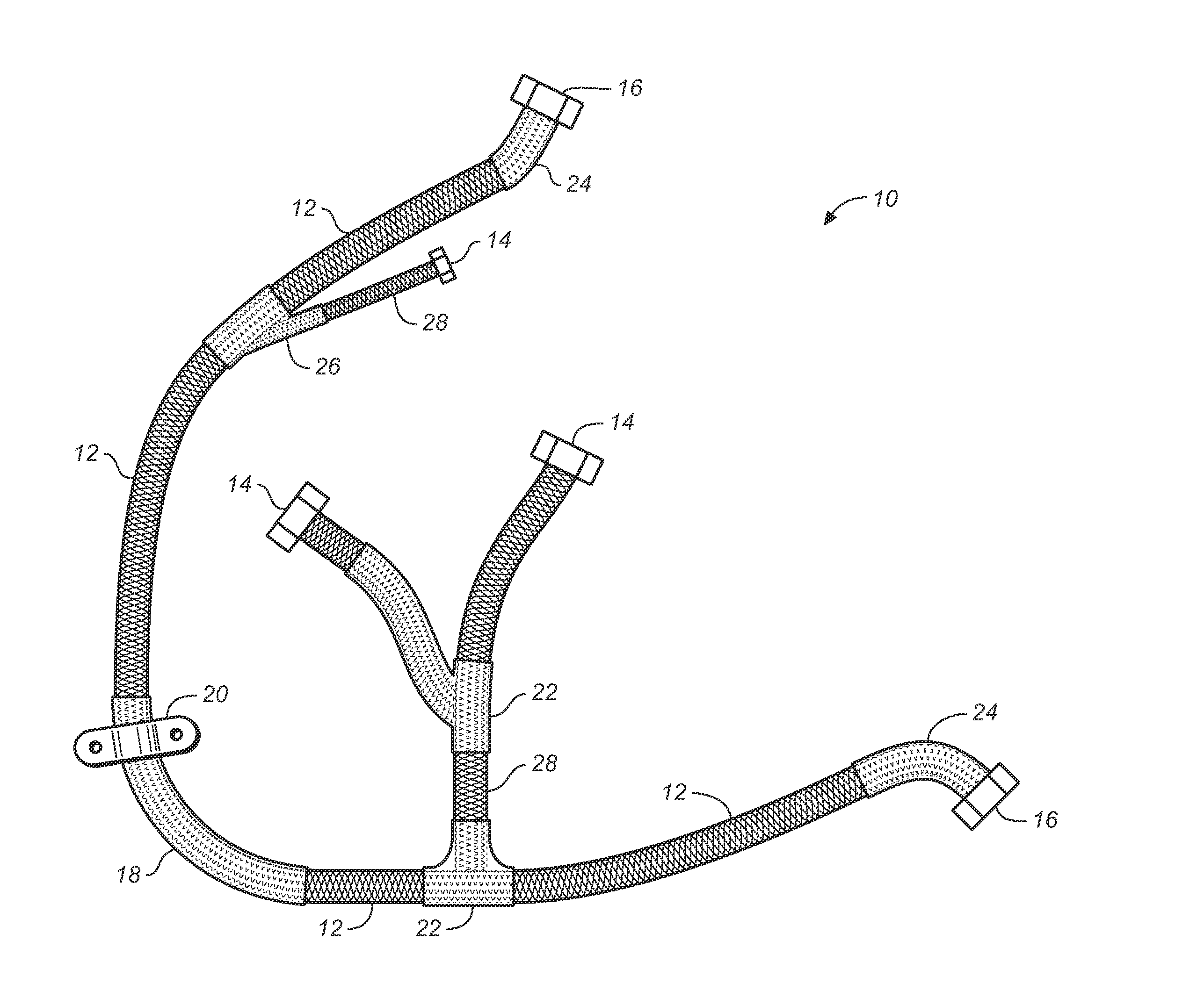
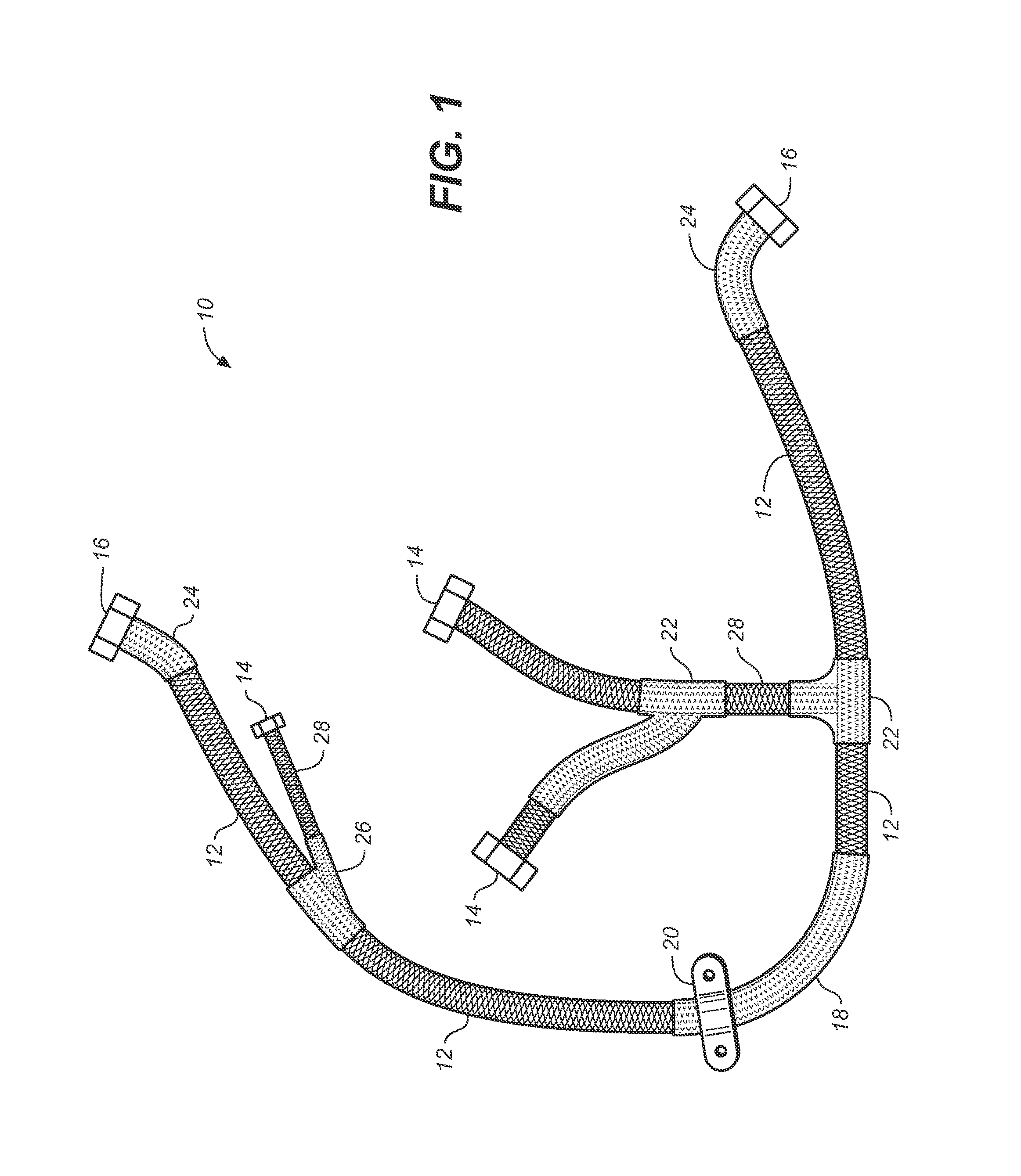
[0012]Referring to FIG. 1, the present invention 10 provides a novel means to rigidify a run of cable or harness in virtually any configuration without the expense and complexity of having to provide multiple fittings and junctions or the need to bend marginally bendable conduit in multiple dimensions. For any given run of cable, the inventive apparatus comprises a length of flexible cable 12 having two, or more, end connectors or fittings 14, 16. In the illustration, the cable is agnostic (of indeterminate type). The structural elements include single or multiple conductor wires and / or coaxial, or multiple conductor cables, and the cable and wires may be shielded with one or two layers of braided metal wire shielding made from stainless steel or copper plated with tin or nickel, and may be covered with a jacket of rubber, elastomer, or heat shrink material. Also, overbraiding may be provided by a durable fabric, such as Dacron® (Dacron is a registered trademark of E. I. Du Pont De ...


PUM

PropertyMeasurementUnit
Lengthaaaaaaaaaa
Lengthaaaaaaaaaa
Flexibilityaaaaaaaaaa

Abstract

A rigidified flexible cable including flexible portions and one or more rigid segments, including a primary flexible cable with ends and end fittings, and at least one rigid medial section integral with the flexible portion and formed by coating the flexible cable material with a composite matrix material. Lateral transitions can be incorporated into the cable run and customized to the installation site specifications.

Description

CROSS REFERENCES TO RELATED APPLICATIONS[0001]The present application claims the benefit of U.S. Provisional Patent Application Ser. No. 61 / 703,728, filed Sep. 20, 2012 (Sep. 20, 2012).STATEMENT REGARDING FEDERALLY SPONSORED RESEARCH OR DEVELOPMENT[0002]Not applicable.THE NAMES OR PARTIES TO A JOINT RESEARCH AGREEMENT[0003]Not applicable.INCORPORATION BY REFERENCE OF MATERIAL SUBMITTED ON A COMPACT DISC[0004]Not applicable.BACKGROUND OF THE INVENTION[0005]1. Field of the Invention[0006]Field of the Invention: The present invention relates most generally to electrical cables, and more particularly to an assembly consisting of a flexible cable with two or more end fittings, one or more multiple leg transitions, and at least one intermediate rigid section, wherein the rigid section is formed around the flexible cable using a fiber reinforced polymeric composite material, thereby eliminating the need for additional fittings for the flexible / rigid portion junctions.[0007]2. Background Di...

Claims


Application Information

Patent Timeline
IPC IPC(8): H01B7/00
CPCH01B7/0045H01B7/24
Inventor MCGRATH, MARKBAEDER, GREGORY S.ANDREWS, SCOTT M.
Owner ICORE INT
Why Eureka
Try Eureka