Power generation control device, photovoltaic power generation system and power generation control method

Inactive Publication Date: 2014-03-20
PANASONIC INTELLECTUAL PROPERTY MANAGEMENT CO LTD
View PDF2 Cites 29 Cited by
  • Summary
  • Abstract
  • Description
  • Claims
  • Application Information

AI Technical Summary

Benefits of technology

[0016]According to the aspect as mentioned above, it is possible to rapidly search for a maximum power point and to suppress a variation in outp

Problems solved by technology

In addition, during the scanning, the output current or the output voltage of the photovoltaic panel greatly varies, whereby electrical appliances connected to the photovoltaic power

Method used


Image

  • Power generation control device, photovoltaic power generation system and power generation control method
  • Power generation control device, photovoltaic power generation system and power generation control method
  • Power generation control device, photovoltaic power generation system and power generation control method

Examples


Example

First Embodiment

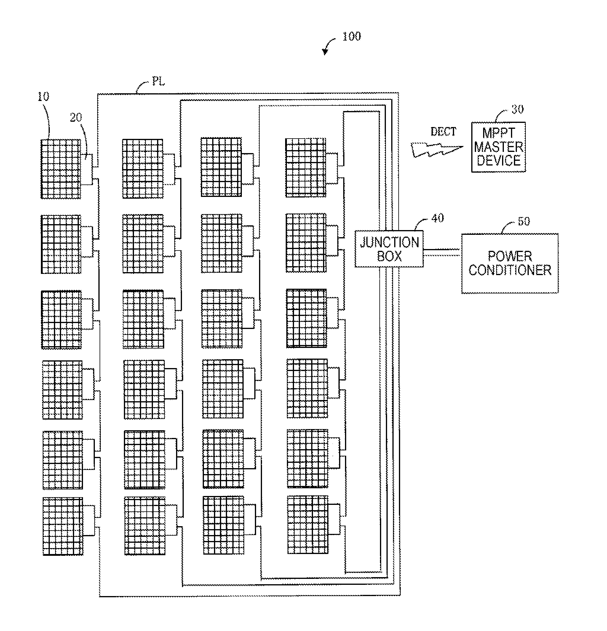
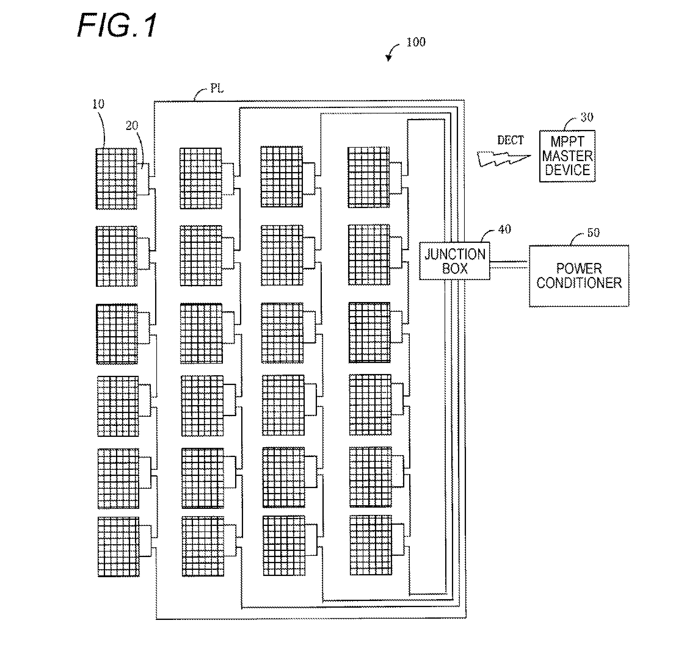
[0052]FIG. 1 is a diagram illustrating a configuration example of a photovoltaic power generation system 100 according to a first embodiment of the present invention. The photovoltaic power generation system 100 includes photovoltaic (PV) panels 10, MPPT slave devices 20, an MPPT master device 30, a junction box 40, and a power conditioner 50. Each MPPT slave device 20 is an example of the power generation control device. The MPPT master device 30 is an example of the control device.

[0053]A PV panel 10 is a panel including photovoltaic cells that converts optical energy into electric power using a photoelectric conversion effect. The PV panel 10 may be a single photovoltaic cell or a photovoltaic cell module in which plural photovoltaic cells are combined. The PV panels 10 are connected in series or in parallel to power lines PL. The PV panels 10 are associated with the MPPT slave devices 20 in a one-to-one manner.

[0054]In the example shown in FIG. 1, the PV panels 1...

Example

Second Embodiment

[0203]First, a background of a second embodiment is explained.

[0204]A photovoltaic power generation system includes plural PV panels, plural MPPT units connected to the PV panels, respectively, and a power conditioner. Each MPPT unit can perform MPPT control so as to maximize the amount of power generated from the PV panel connected thereto. The power conditioner can perform MPPT control so as to maximize the total amount of power generated from all the plural PV panels.

[0205]FIG. 31A is a diagram illustrating an IV (Current-Voltage) characteristic of a PV panel when an MPPT unit does not perform the MPPT control. FIG. 31B is a diagram illustrating a PV (Power-Voltage) characteristic of a PV panel when an MPPT unit does not perform the MPPT control. As shown in FIGS. 31A and 31B, when the MPPT control is not performed, a single maximum power point is determined.

[0206]FIG. 31C is a diagram illustrating an ideal PV characteristic of a PV panel when an MPPT unit perfor...


PUM


Abstract

A power generation control device is electrically connected to a photovoltaic panel for controlling an output voltage of the photovoltaic panel. The power generation control device includes a scanning unit, configured to perform a scanning process in which the output voltage of the photovoltaic panel is sequentially changed in a predetermined voltage range. The predetermined voltage range is changed in accordance with the photovoltaic panel.

Description

BACKGROUND[0001]1. Technical Field[0002]The present invention relates to a power generation control device, a photovoltaic power generation system, a power generation control method, a control device, and a control method.[0003]2. Background Art[0004]In recent years, photovoltaic power generation of converting solar energy into electric energy using a photovoltaic (PV) panel has been spread widely for conventional use. The photovoltaic power generation has recently particularly attracted attention because waste materials, waste water, noise, vibration, and the like are not generated at the time of power generation and thus the photovoltaic power generation is expected to be commercially used as an emergency power source.[0005]The power generation capacity of a photovoltaic panel depends on, for example, solar irradiance and weather (for example, temperature and cloudiness). In order to maximize the power generated in the photovoltaic power generation, maximum power point tracking (M...

Claims


Application Information

Patent Timeline
IPC IPC(8): H02J1/10
CPCH02J1/102G05F1/67H02M3/1582H02J2300/26H02J3/381Y02E10/56H02J3/46
Inventor NOSAKA, SHIGEKIYOYANAGI, KAZUHIRO
Owner PANASONIC INTELLECTUAL PROPERTY MANAGEMENT CO LTD
Why Eureka
Try Eureka