Driving System For Synchronous Motor

a technology of synchronous motors and driving systems, applied in the direction of motor/generator/converter stoppers, electronic commutators, dynamo-electric converter control, etc., can solve the problems of reduced sensitivity, hidden position information in noise, and large problem of sensor-less control, etc., to achieve the effect of increasing the number of switching and high efficiency

Inactive Publication Date: 2014-03-20
HITACHI LTD
View PDF6 Cites 26 Cited by
  • Summary
  • Abstract
  • Description
  • Claims
  • Application Information

AI Technical Summary

Benefits of technology

[0029]According to a driving system for a three-phase synchronous motor concerning a desired embodiment of the present invention, sensor-less driving with a sinusoidal current can be achieved at a speed as low as an extremely low speed region which is close to zero speed.
[0030]According to a driving system for a three-phase synchronous motor concerning a desired embodiment of the present invention, a driving system for a synchronous motor that can drive with a high degree of efficiency can be provided without increasing the number of switching.

Problems solved by technology

These sensor-less controls also involve great problem.
Therefore, in a stopped or low speed region in which the induced voltage is small, the sensitivity is reduced, and the position information may be buried in the noise.

Method used


Image

  • Driving System For Synchronous Motor
  • Driving System For Synchronous Motor
  • Driving System For Synchronous Motor

Examples


first embodiment

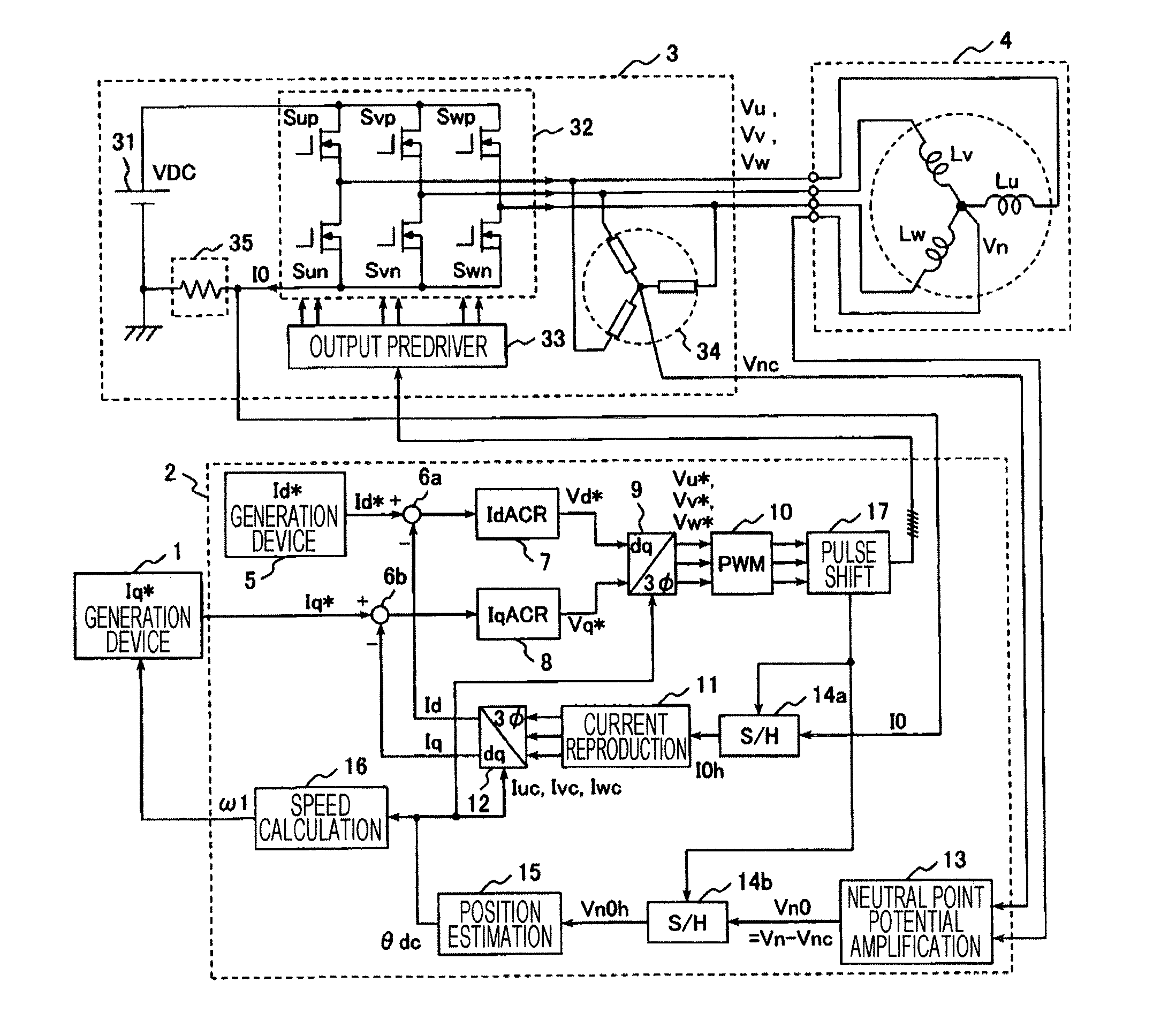
[0060]FIG. 1 is a block diagram illustrating a configuration of a motor driving system according to a first embodiment of the present invention.

[0061]An object of this motor driving system is to drive a permanent magnet motor (three-phase synchronous motor) 4. Roughly speaking, this motor driving system includes an Iq* generation device 1, a control device 2, an inverter main circuit 32, an inverter 3 including a one-shunt current detection device 35, and a permanent magnet motor 4 which is target of driving.

[0062]The Iq* generation device 1 is a circuit for generating a current command Iq* corresponding to torque of an electric motor. This Iq* generation device 1 is a control device located above the control device 2. Usually, this has a mechanism of generating required current command Iq* by observing an actual speed ω1 so that the rotation speed of the permanent magnet motor 4 attains a predetermined speed. The current command Iq* which is output of the Iq* generation device 1 is...

second embodiment

[0115]Subsequently, the second embodiment of the present invention will be explained.

[0116]In the first embodiment, in order to detect Vn0, the pulse shift device 17 is introduced to shift the PWM pulse wave, whereby the output periods of the voltage vectors other than zero vector are increased, and two kinds of vector not included in the original PWM waveforms can be newly output, and therefore, the precision of the position estimation is improved.

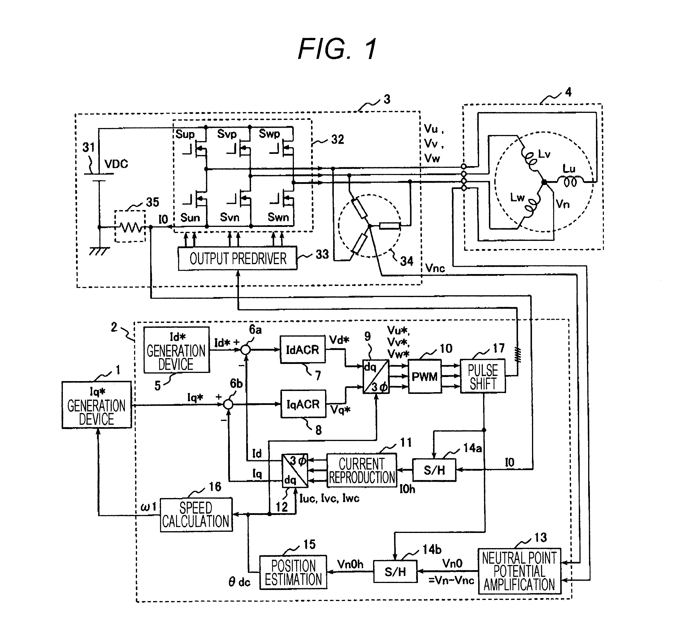
[0117]In the example of the first embodiment, not only the original voltage vectors V (0, 0, 1), V (1, 0, 1) but also V (1, 1, 0), V (0, 1, 0) are newly applied. In this case, it is understood from FIG. 2(a) that V (0, 0, 1) and V (1, 1, 0) are vectors in direction opposite to V (1, 0, 1) and V (0, 1, 0), respectively. As described above, not only the vectors in the opposite direction but also voltage vector in a direction not included in PWM before the pulse shift, e.g., V (1, 0, 0) are added, this makes the effect of search of the rotor...

third embodiment

[0120]Subsequently, the third embodiment of the present invention will be explained with reference to FIG. 7.

[0121]The first and second embodiments showed that the pulse shift device 17 is introduced, so that the types of voltage vectors applied to the motor can be increased from two types to three or four types. In these embodiments, the switches of all of the three phases perform switching with the same frequency as the triangle wave carrier. In contrast, in the third embodiment, an example where the switching frequencies of the three phases are different (two-phase switching) will be explained.

[0122]FIG. 7(a) shows two-phase switching method using triangle wave carrier. Unlike FIG. 4, it is understood that the three-phase voltage commands Vu*, Vv*, Vw* are in contact with the upper side peak of the triangle wave carrier. In this example, Vw* which is the largest among the three-phase voltage commands matches the upper side peak value of the triangle wave carrier. In this manner, ...


PUM


Abstract

A position sensor-less driving method is provided that can drive rotation speed / torque control of a permanent magnet motor using an inverter with an ideal sinusoidal current with the minimum number of switching, and can drive at a speed as low as an extremely low speed region close to zero speed. A neutral point potential of a permanent magnet motor is detected in synchronization with PWM waveform of the inverter. A rotor position of the permanent magnet motor is estimated from change of the neutral point potential. When the neutral point potential is detected, timing of each phase of the PWM waveform is shifted to generate three or four types of switch states of which output voltage of the inverter is not zero vector, and neutral point potentials in at least two types of switch states among them are sampled, whereby rotor position of the three-phase synchronous motor is estimated.

Description

TECHNICAL FIELD[0001]The present invention relates to a driving system for a synchronous motor used for controlling torque such as a motor driving device, for example, rotation speed control for a fan, a pump, a compressor, and a spindle motor, a positioning apparatus for a conveyer and a machine tool, and electric-power assisting.BACKGROUND ART[0002]In various kinds of fields such as industrial, home electronic appliances, and automobiles, small and highly-efficient permanent magnet motors (three-phase synchronous motors) are widely used.[0003]However, in order to drive the permanent magnet motor, it is necessary to have position information of the rotor of the motor, and a position sensor therefor is required. In recent years, sensor-less control is widely prevalent, in which this position sensor is eliminated, and the torque control and the rotation speed of the permanent magnet motor are controlled.[0004]As the sensor-less control is put into practice, the expenses concerning th...

Claims


Application Information

Patent Timeline
Patent Type & Authority Applications(United States)
IPC IPC(8): H02P6/18H02P6/06H02P6/08H02P6/17H02P6/182H02P6/28H02P21/00H02P21/14H02P21/18H02P21/22H02P21/24H02P21/28H02P23/14H02P23/16H02P23/18H02P27/04H02P27/08
CPCH02P6/187H02P27/08H02P21/04H02P21/24
Inventor IWAJI, YOSHITAKAAOYAGI, SHIGEHISATAKAHATA, RYOICHITOBARI, KAZUAKI
Owner HITACHI LTD
Why Eureka
Try Eureka