High speed tool steel, material for blade edge, cutting tool, and manufacturing method of material for blade edge

Active Publication Date: 2014-03-20
HITACHI METALS LTD
View PDF0 Cites 9 Cited by
  • Summary
  • Abstract
  • Description
  • Claims
  • Application Information

AI Technical Summary

Benefits of technology

The present invention provides a method to make structures with fine carbides using high speed tool steel. This results in excellent chipping resistance when used in cutting tools. This high speed tool steel is suitable for use as a blade edge material for cutting tools and, in particular, for saw blades. The method can also be used to manufacture this material.

Problems solved by technology

However, it is known that, depending on a condition of use, early wear, chipping and the like of the blade edge can occur as forms of wear and breakage limited to the blade edge.
However, chipping can still occur at an early stage.
A stress (fracture stress) required to break the blade edge during use decreases, and fracture originating from a coarse carbide occurs.
However, when the eutectic carbides are in a significantly coarse massive form, in a manufacturing process of the material for the blade edge, even by successive hot working (wire rod processing), the carbides cannot be changed to be sufficiently granular, so that, in an annealed structure of the material for the blade edge, there is a large amount of the significantly coarse carbides having an absolute maximum length of 25 μm or more.
As a result, this becomes a main reason why a saw blade containing a large amount of coarse carbides in a blade edge structure has excellent wear resistance, but chipping resistance of the saw blade deteriorates.
However, for the material for the blade edge according to the conventional technology, reducing the size of the carbides in a structure is not necessarily easy.
The reason is that, in order to achieve efficiency in an actual operation, it is necessary to increase a weight of the source material such as steel ingots or billets so that a cooling rate slows down when molten steel solidifies, and thus undesirable coarse eutectic carbides are formed in a cast structure of the source material after solidification and remain until a subsequent process.

Method used


Image

  • High speed tool steel, material for blade edge, cutting tool, and manufacturing method of material for blade edge
  • High speed tool steel, material for blade edge, cutting tool, and manufacturing method of material for blade edge
  • High speed tool steel, material for blade edge, cutting tool, and manufacturing method of material for blade edge

Examples


first embodiment

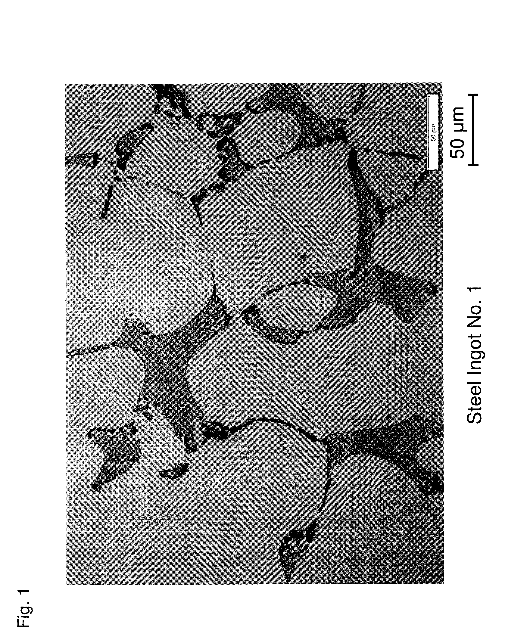
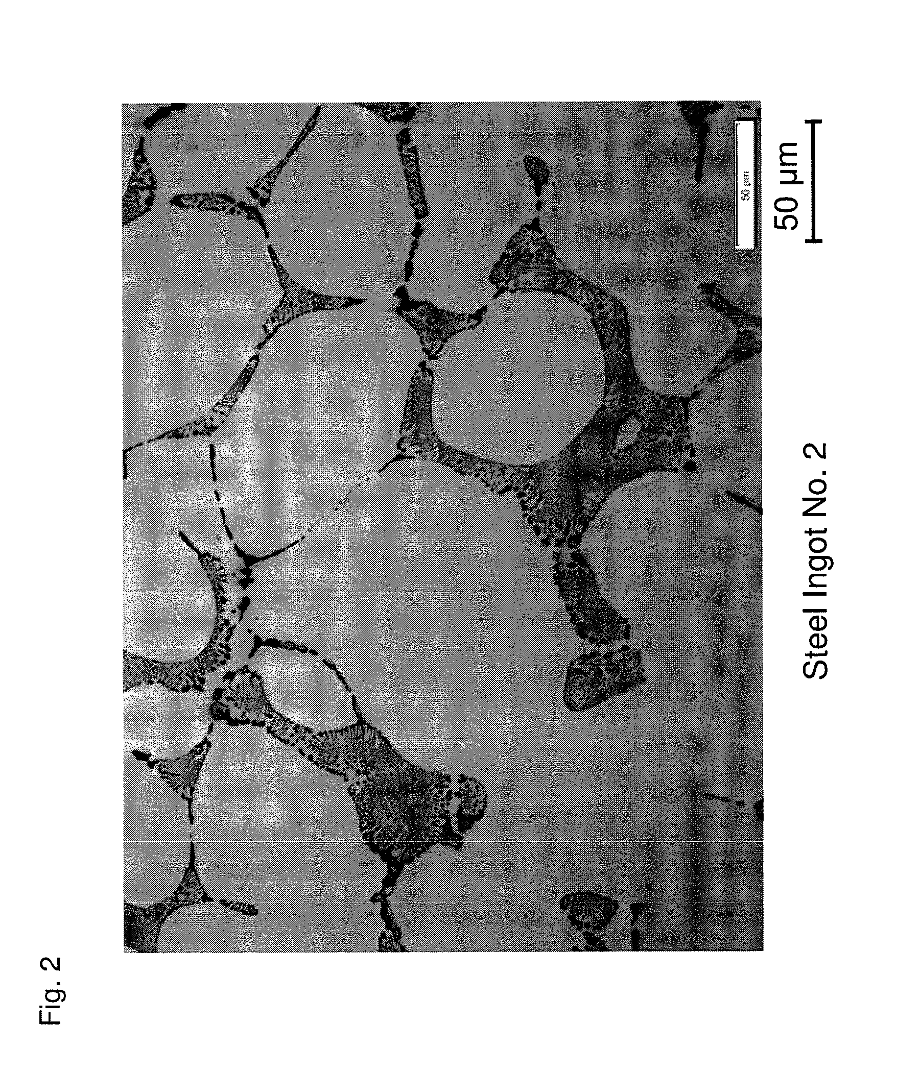
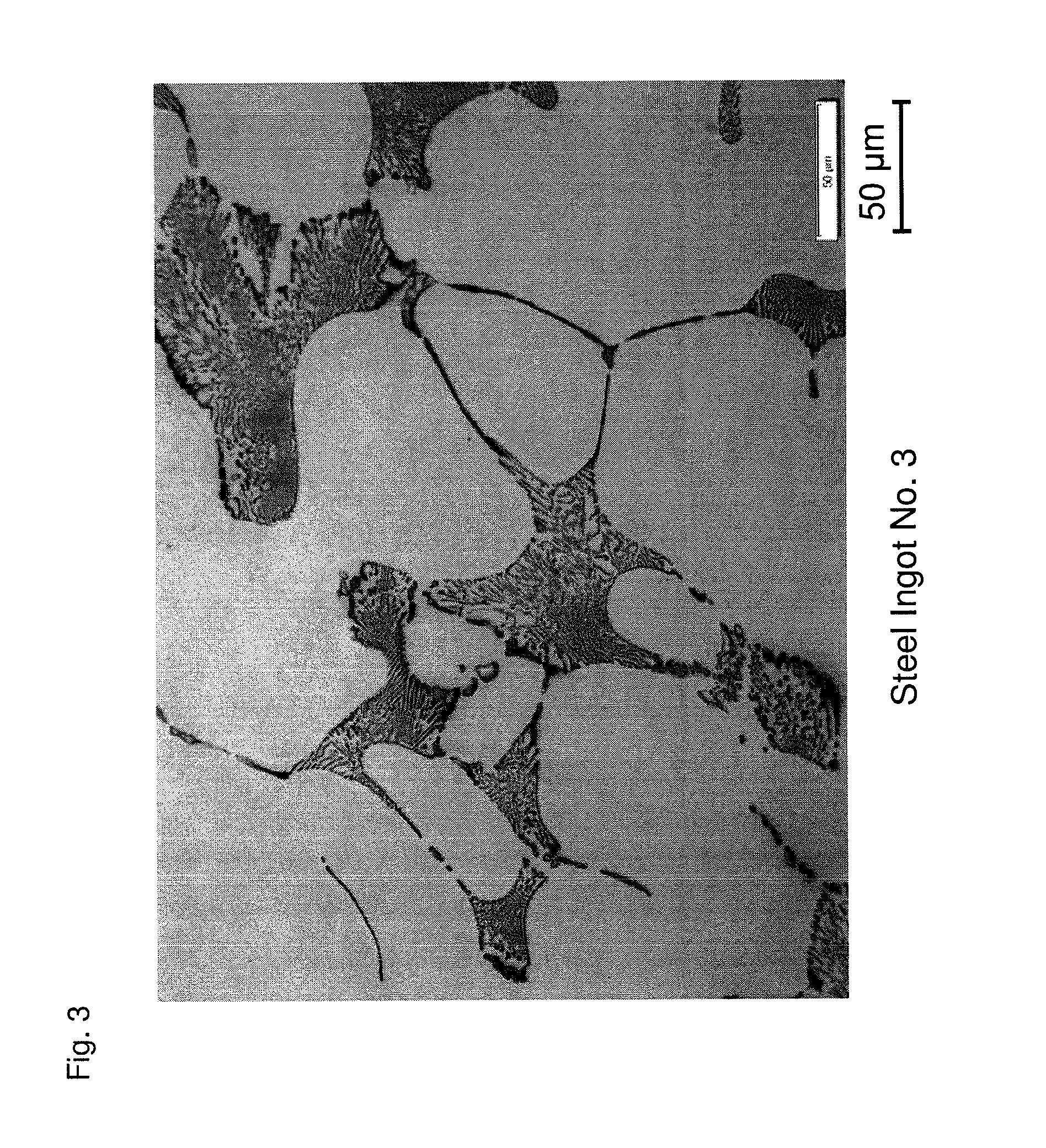
[0044]A molten steel adjusted to a predetermined component composition is prepared. The amount of N in the molten steel is adjusted by vacuum refining and introducing a CrN alloy. The amount of Ca in the molten steel is adjusted by introducing a Ca—Si alloy. Next, the molten steel is cast at a cooling rate of about 10° C. / minute, which corresponds to an actual operation level, to fabricate a steel ingot of a high speed tool steel having a component composition as illustrated in Table 1.

TABLE 1SteelComponent Composition (mass %) * [Ca] and [N] (ppm)Ingot No.CSiMnPSCrWMoVCo[Ca][N]Remarks11.080.310.280.0190.00193.811.419.361.107.901159Examples of21.080.330.290.0240.00153.811.389.411.097.949108Present31.080.310.290.0230.00153.821.399.321.137.849125Invention41.070.320.300.0240.00133.801.419.311.117.90296051.060.310.290.0200.00163.791.419.331.117.902910361.080.320.300.0230.00153.801.429.381.137.872412571.070.330.300.0230.00183.861.409.351.107.8962Comparative81.080.320.290.0240.00153.801.4...

second embodiment

[0049]Assuming a case where the high speed tool steel of the present invention is used as a blade edge of a cutting tool, in order to evaluate the chipping resistance in this case, a bending test of three-point bending is performed. A bending test specimen is prepared in the following manner. First, a molten steel adjusted to a predetermined component composition is prepared. The amount of N in the molten steel is adjusted by degassing refinement. The amount of Ca in the molten steel is adjusted by introducing a Ca—Si alloy. Next, the molten steel is cast at a cooling rate of about 10° C. / minute, which corresponds to an actual operation level, to fabricate a steel ingot of a high speed tool steel having a component composition as illustrated in Table 3. For these steel ingots, distributions of eutectic carbides in structures of the steel ingots No. 14 and No. 15 are, respectively, substantially equal to those of the steel ingots No. 2 and No. 9 of the first embodiment.

TABLE 3SteelCo...


PUM


Abstract

A high speed tool steel containing, by mass percent, 0.5-1.5% of C; 1.0% or less of Si; 1.0% or less of Mn; 3.0-5.0% of Cr; 15.0-25.0% of one or two kinds of W and Mo according to a formula (W+2Mo); 1.0-less than 1.5% of V; 5.0-10.0% of Co; and a remainder including Fe and impurities, the high speed tool steel further containing 0.0005-0.004% of Ca and 0.005-0.015% of N. Also, a material for a blade edge that is made of the high speed tool steel and a cutting tool made by welding the material for the blade edge to a body material. Further, a manufacturing method of the material for the blade edge.

Description

CROSS-REFERENCE TO RELATED APPLICATIONS[0001]The present application claims priority under 35 U.S.C. §119 of Japanese Application No. 2012-206562, filed on Sep. 20, 2012, and of Japanese Application No. 2013-063778, filed on Mar. 26, 2013, the disclosures of which are expressly incorporated by reference herein in their entirety.BACKGROUND OF THE INVENTION[0002]1. Field of the Invention[0003]The present invention relates to a high speed tool steel, a material for a blade edge, a cutting tool, and a manufacturing method of the material for the blade edge, the high speed tool steel being suitable as a source material for the material for the blade edge of the cutting tool such as a saw blade used in cutting a metal.[0004]2. Description of Related Art[0005]Conventionally, in cutting a metallic material such as steel, a cutting tool is used, a typical example of which is a saw blade such as a band saw and a circular saw. The saw blade is manufactured in general by the following process. ...

Claims


Application Information

Patent Timeline
IPC IPC(8): C22C38/30C22C38/24C22C38/00C22C38/04C22C38/02B26D1/00C22C38/22
CPCC22C38/30B26D1/0006C22C38/24C22C38/001C22C38/04C22C38/02C22C38/002C22C38/22B23D61/127B23D65/00C21D1/25C21D6/002C21D9/22C21D2211/004
Inventor FUKUMOTO, SHIHO
Owner HITACHI METALS LTD
Why Eureka
Try Eureka