Energy storage thermal management system using multi-temperature phase change materials

a phase change material and energy storage technology, applied in the field of battery power supply, can solve the problems of thermal runaway, premature failure of a specific cell element or an associated cell pack or module, and affecting the performance of the device, so as to improve the efficiency of thermal energy removal, enhance heat transfer, and melt the effect of temperatur

Active Publication Date: 2014-03-20
BEAM GLOBAL
View PDF4 Cites 64 Cited by
  • Summary
  • Abstract
  • Description
  • Claims
  • Application Information

AI Technical Summary

Benefits of technology

[0013]In one embodiment of this invention, the energy storage system includes two different phase change materials (e.g., each having a different phase change temperature) to improve efficiency of thermal energy removal. In one embodiment, the energy storage components (e.g., batteries, capacitors, etc) will be surrounded by one phase change material (“PCM”) that has a higher melting temperature than a second PCM. The melting point of this first PCM will desirably be designed to be below the maximum allowable component temperature determined according to need by the system designers. The primary PCM will absorb heat generated by the energy storage components and will reject heat to the secondary PCM. The secondary PCM will have a melting temperature above the expected surrounding air temperature but below the primary PCM melting temperature. The enforced temperature gradient between the two PCMs will enhance heat transfer by allowing for heat conduction between the two PCMs rather than relying solely upon convection from the heat transfer fluid. The dual melting temperature approach also allows for heat flow from the secondary PCM to the primary PCM during transient periods in cold ambient conditions.

Problems solved by technology

During operation and discharge, such cells, battery modules, or battery packs commonly produce or generate quantities of heat which can significantly detrimentally impact the performance that results therefrom.
Such capacity imbalances can cause or result in some cells being over-charged or over-discharged which in turn may result in premature failure of a specific cell element or of an associated cell pack or module.
In particular, such failures may take the form of thermal runaway or accelerating capacity fading.
It will be appreciated, however, that the incorporation and use of internal active cooling regimes may introduce undesired weight and / or a level of complexity in either or both power supply design and operation and such as may hinder or prevent the more widespread use of such corresponding power supply systems.

Method used


Image

  • Energy storage thermal management system using multi-temperature phase change materials
  • Energy storage thermal management system using multi-temperature phase change materials
  • Energy storage thermal management system using multi-temperature phase change materials

Examples


Embodiment Construction

[0022]U.S. Pat. Nos. 6,468,689 and 6,942,944, herein incorporated by reference, are directed to thermal management of battery systems. Aspects and advantages of this invention can be applied to battery systems such as disclosed in these Patents. Likewise, materials and features disclosed in these Patents can be incorporated in the systems according to this invention.

[0023]The present invention generally provides an improved power supply system and method of operation. More particularly, the invention provides an improved power supply system and method of operation such that provide or result in improved thermal management such as wherein undesired temperature excursions and non-uniformity of temperature can be appropriately reduced, minimized, or otherwise suitably managed.

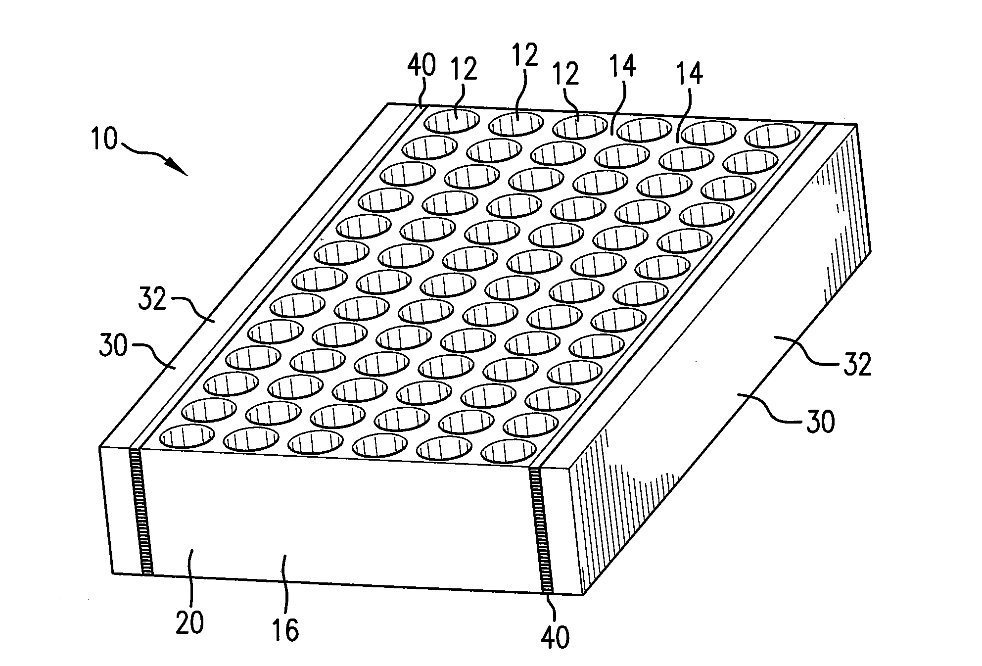
[0024]The present invention may be embodied in a variety of different structures. FIG. 1 illustrates the present invention as embodied in a battery module, generally designated by the reference numeral 10. The bat...


PUM

PropertyMeasurementUnit
melting temperatureaaaaaaaaaa
temperatureaaaaaaaaaa

Abstract

A thermal management method and system for energy storage devices, such as devices including an array of electro-chemical cell elements. A first phase change material is in heat-transferring thermal contact with the electrochemical cell elements. A second phase change material in heat-transferring thermal contact with the first phase change material. A heat exchange path can be disposed between the first phase change material and the second phase change material.

Description

CROSS REFERENCE TO RELATED APPLICATION[0001]This application claims priority to or the benefit of U.S. Provisional Patent Application, Ser. No. 61 / 494,176, filed on 7 Jun. 2011. The co-pending provisional application is hereby incorporated by reference herein in its entirety and is made a part hereof, including but not limited to those portions which specifically appear hereinafter.BACKGROUND OF THE INVENTION[0002]This invention relates generally to battery power supply and, more particularly, to thermal management in such battery power supply systems. The word “battery” here is meant to include various forms of electrochemical power generation which have in common that chemical energy, in the form of one or more chemical reactants stored in a confined space, react with each other or with an external reactant in an electrochemical reaction, so as to produce electric power when desired.[0003]Various uses of battery power supplies have been well established. For example, the packaging...

Claims


Application Information

Patent Timeline
Patent Type & Authority Applications(United States)
IPC IPC(8): H01M10/50
CPCH01M10/5016H01M10/5048H01M10/0525H01M10/613H01M10/625H01M10/643H01M10/6552H01M10/659Y02E60/10
Inventor AL-HALLAJ, SAIDALBRIGHT, GREG
Owner BEAM GLOBAL
Why Eureka
Try Eureka