Permanent Magnet Centering System for Brake

a permanent magnet and brake technology, applied in the field of brake system, can solve the problems of stictional and frictional losses, adding to the overall cost and maintenance of the disc brake, and not being able to meet the needs of the caliper, and achieve the effect of facilitating the centering of the fixed elemen

Active Publication Date: 2014-04-03
OTIS ELEVATOR CO
View PDF7 Cites 3 Cited by
  • Summary
  • Abstract
  • Description
  • Claims
  • Application Information

AI Technical Summary

Benefits of technology

[0007]In accordance with one aspect of the present disclosure, a brake assembly is disclosed. The brake assembly may include a rotating element, a fixed element mounted in operational association with the rotating element a

Problems solved by technology

However, this typically is not the case.
Although effective, such traditional techniques nonetheless have several disadvantages.
These sensors maintain substantial physical contact with the rotors, resulting in stictional and frictional losses.
Often such techniques also require a power supply or ot

Method used


Image

  • Permanent Magnet Centering System for Brake
  • Permanent Magnet Centering System for Brake
  • Permanent Magnet Centering System for Brake

Examples


Embodiment Construction

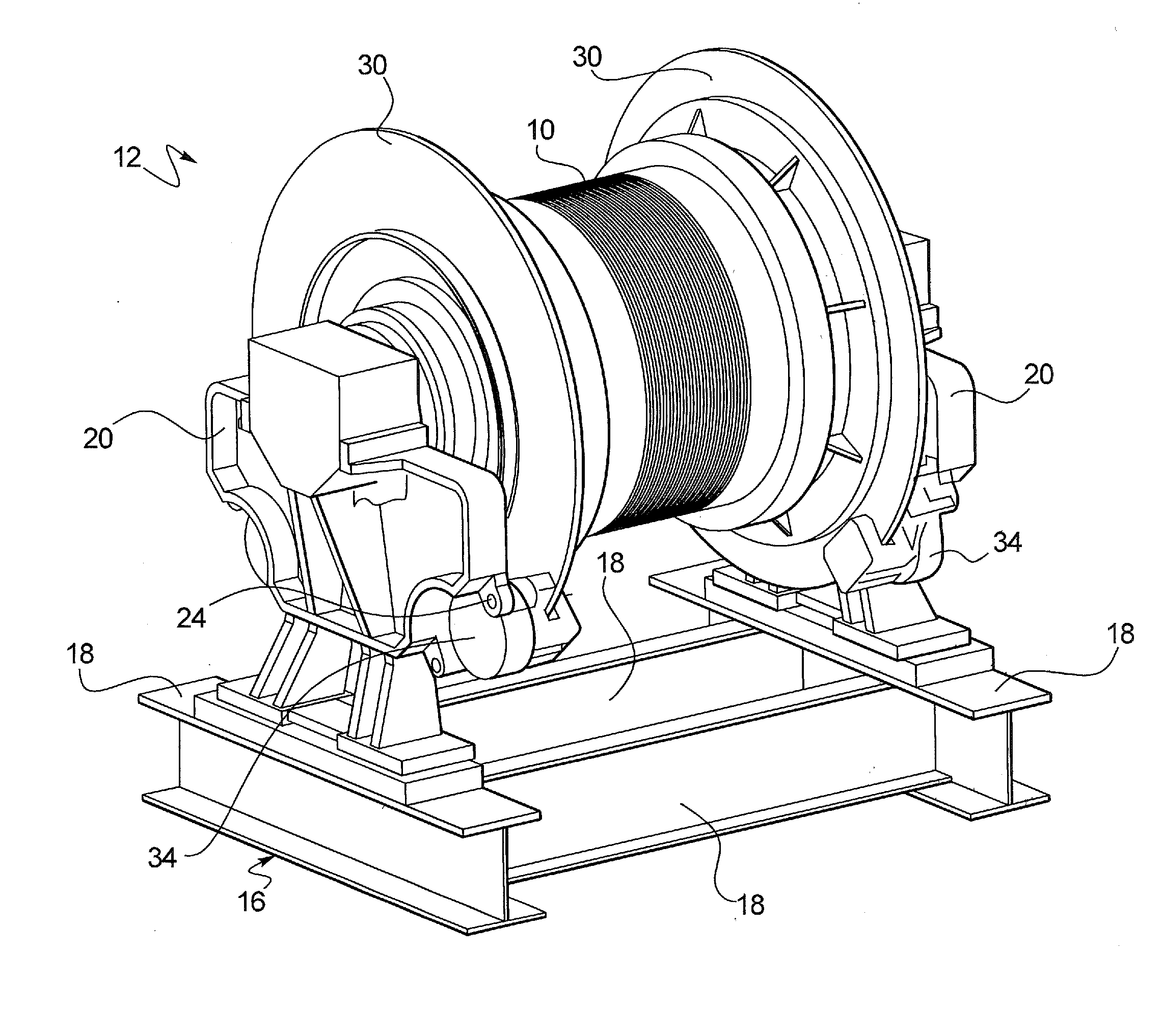
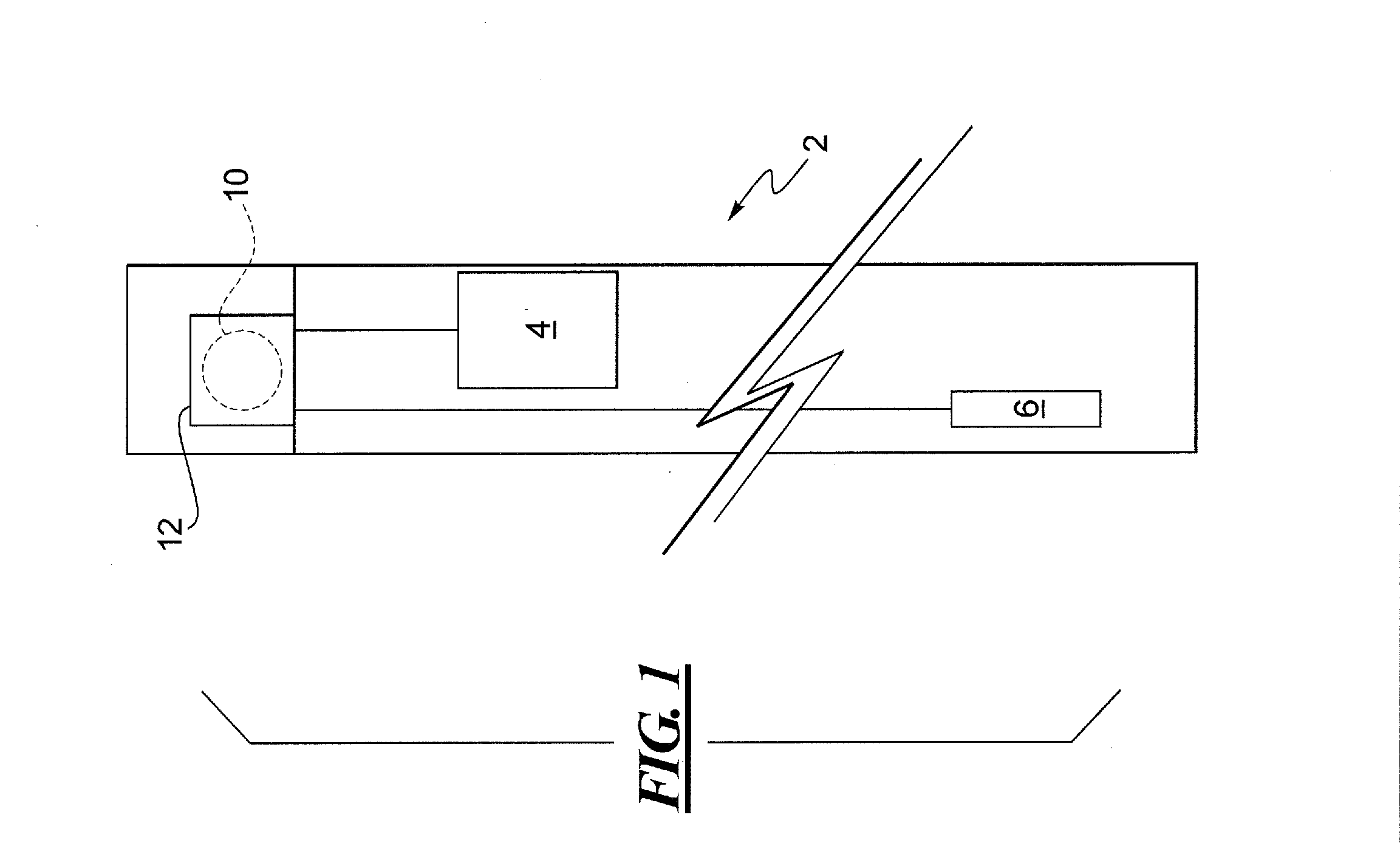
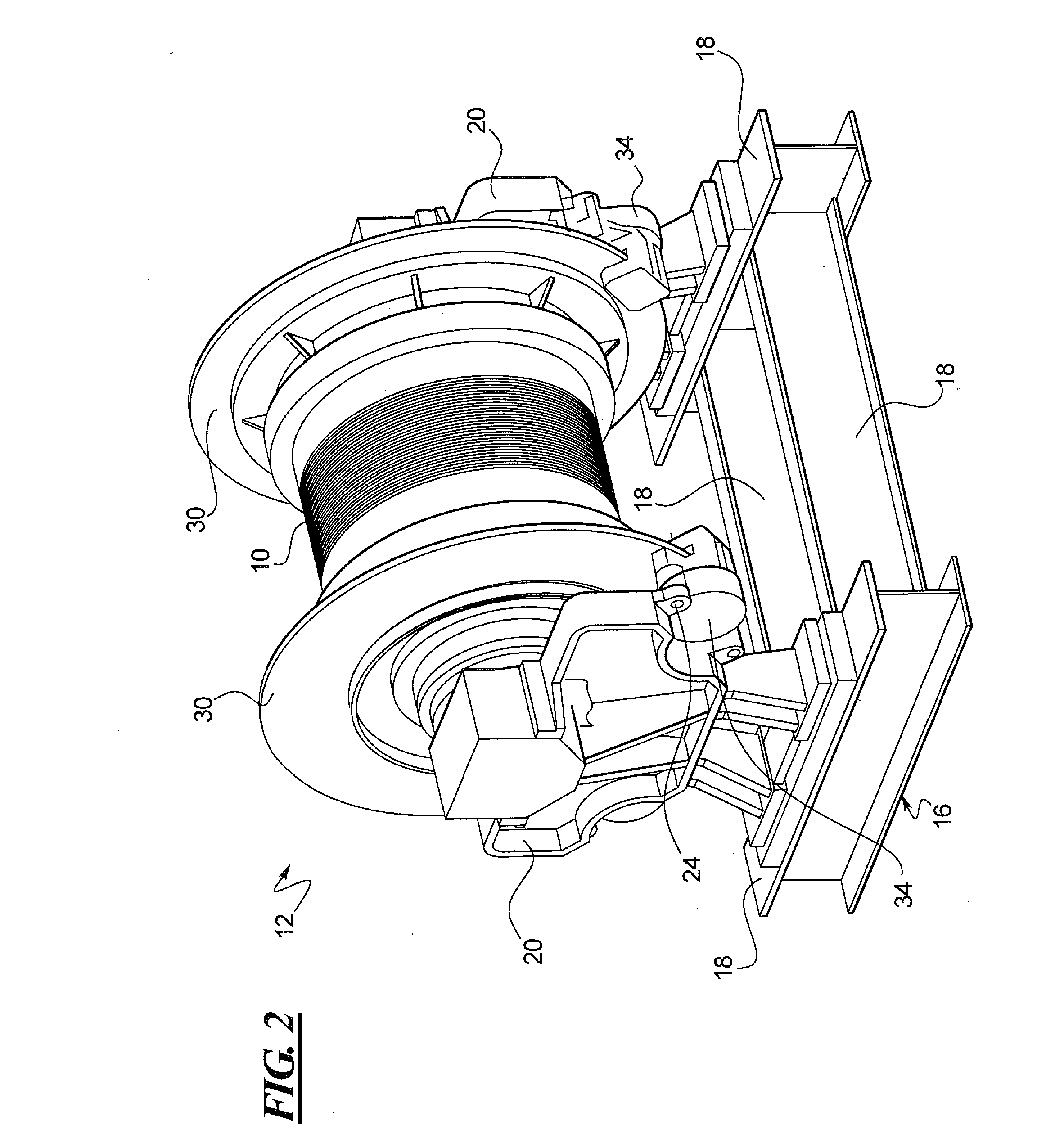
[0030]Referring now to FIG. 1, a simplified schematic representation of an elevator system 2 is shown, in accordance with at least some embodiments of the present disclosure. While all of the components of the elevator system 2 have not been shown and / or described in detail herein, a typical elevator system may include an elevator car 4 connected to a counterweight 6 via hoisting ropes (not shown). The hoisting ropes may extend over a traction sheave 10 driven by an electric motor within the traction sheave (e.g., the traction sheave 10 may be the rotor of the electric motor) to move or halt the elevator car 4 as desired. A disc brake system (described below) on the traction sheave 10 helps slow or halt the elevator system 2. The electric motor, the traction sheave 10 and the disc brake system are collectively referred to herein as an elevator traction machine 12. The elevator system 2, with the counterweight 6, operates in a known manner and is therefore, not described in detail fo...


PUM


Abstract

A brake assembly for an elevator traction machine is disclosed. The brake assembly may include a rotating element, a fixed element mounted in operational association with the rotating element and a positioning device connected to the fixed element. The positioning device may additionally magnetically interface with the rotating element to facilitate centering of the fixed element relative to the rotating element.

Description

FIELD OF THE DISCLOSURE[0001]The present disclosure generally relates to brake systems and, more particularly, relates to centering of a caliper relative to a rotor in a disc brake system.BACKGROUND OF THE DISCLOSURE[0002]Disc brakes are widely used for slowing or stopping rotation of an object in motion. One application of a disc brake is an elevator system and, particularly, a traction-based elevator system. Such elevator systems generally include an elevator car connected to a counterweight through hoisting ropes trained around a traction sheave. The traction sheave is driven by a motor such that rotation of the traction sheave moves the hoisting rope, thereby causing desired movement of the elevator car. To slow or halt the motion of the elevator car (e.g., by actuating a brake), the traction sheave is connected to a disc brake.[0003]The traction sheave can be coupled on each side with a flange that acts as a rotating disc or rotor of the disc brake. The traction sheave and the ...

Claims


Application Information

Patent Timeline
IPC IPC(8): F16D65/00B66B11/04F16D55/22
CPCF16D65/005B66B11/04F16D55/22B66D5/14B66D5/30F16D65/12F16D2129/065B66B11/08F16D55/28
Inventor PIECH, ZBIGNIEWWHEELER, ROBERT
Owner OTIS ELEVATOR CO
Why Eureka
Try Eureka