Supercharge Your Innovation With Domain-Expert AI Agents!

Synchronous rectifying buck-boost converter

Active Publication Date: 2014-04-03
INNOTECH CO LTD
View PDF11 Cites 0 Cited by
  • Summary
  • Abstract
  • Description
  • Claims
  • Application Information

AI Technical Summary

Benefits of technology

The patent is about a new type of converter that helps to reduce power loss during energy conversion. It uses two transistors that have low resistance, which means that only a small amount of power is lost during the process. The converter is controlled by a firmware program that allows it to easily obtain and perform the desired functions. This invention makes it easier to modify and apply the converter for different applications.

Problems solved by technology

It is noted that the diodes of the conventional technique encounter a relatively high resistivity and if the same is applied to a conversion circuit in a high electrical field may result in high power loss.

Method used


Image

  • Synchronous rectifying buck-boost converter
  • Synchronous rectifying buck-boost converter
  • Synchronous rectifying buck-boost converter

Examples


Embodiment Construction

[0021]The accompanying drawings are included to provide a further understanding of the invention, and are incorporated in and constitute a part of this specification. The drawings illustrate embodiments of the invention and, together with the description, serve to explain the principles of the invention.

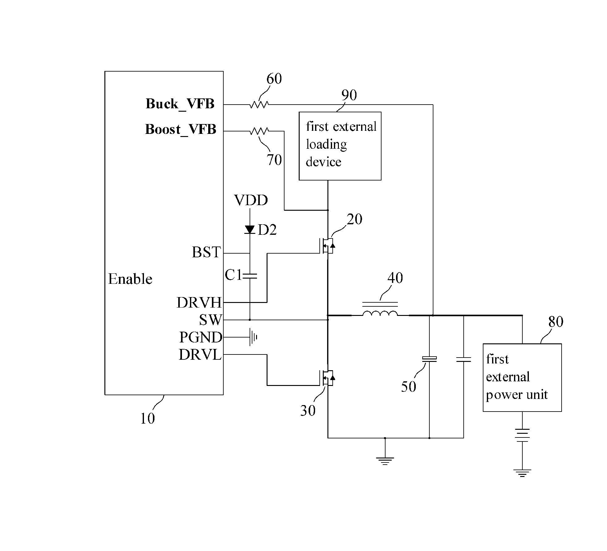
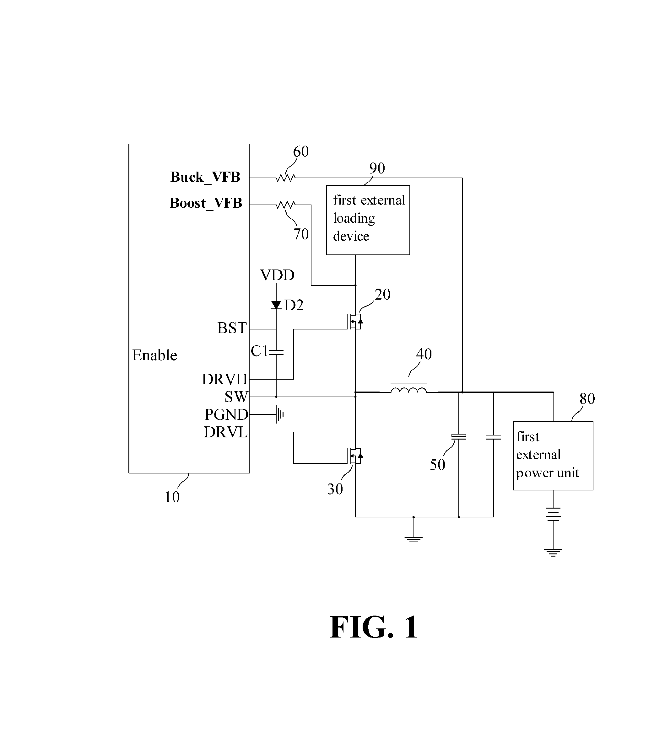
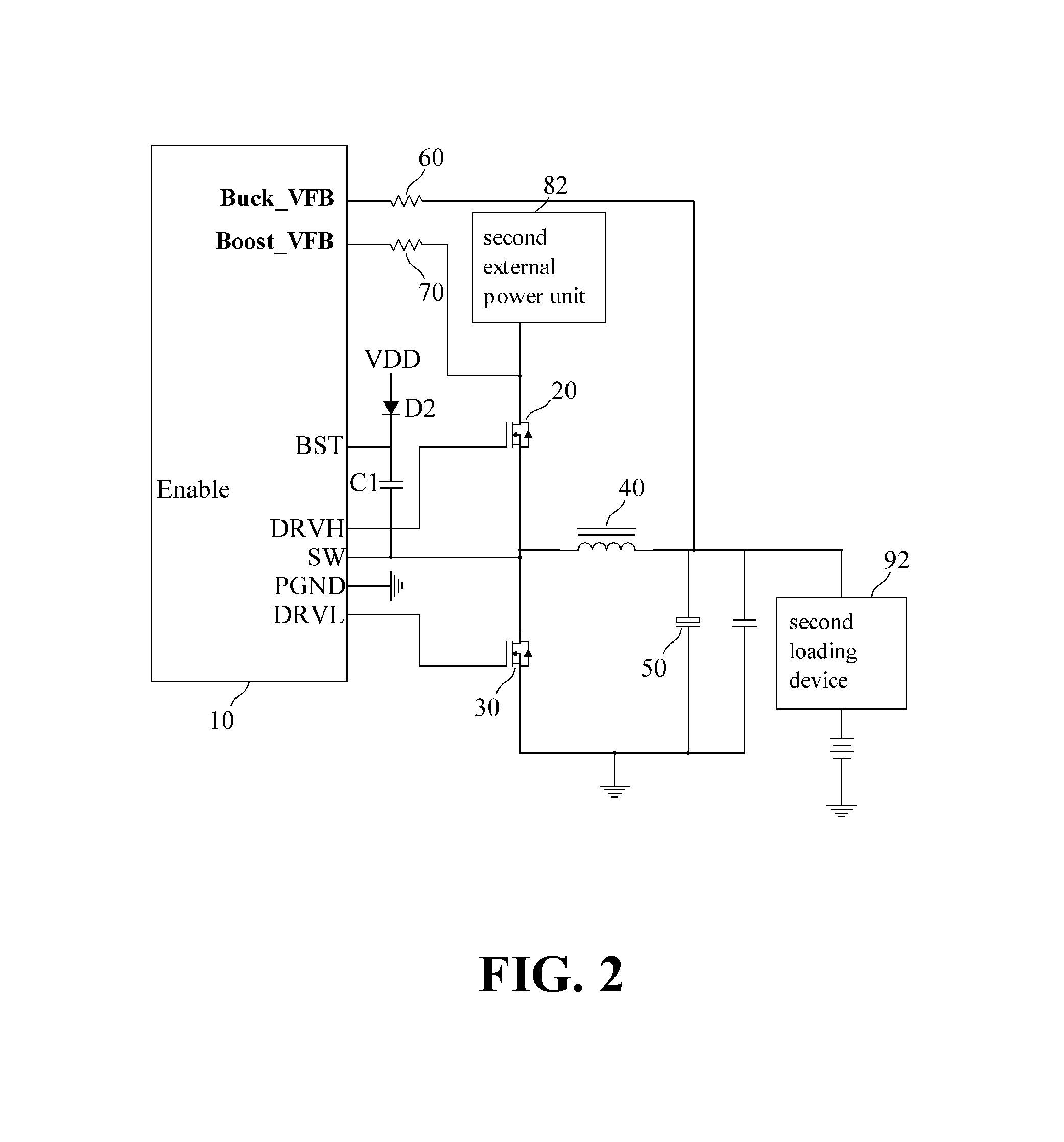
[0022]Referring to FIGS. 1 and 2, wherein FIG. 1 illustrates the first embodiment of a synchronous rectifying buck-boost converter of the present invention in a voltage boost function and FIG. 2 illustrates the first embodiment of the synchronous rectifying buck-boost converter of the present invention in a voltage buck function. As best shown in FIG. 1, the synchronous rectifying buck-boost converter of the present invention includes a controller 10, a first transistor 20, a second transistor 30, an inductor 40, a capacitor 50, a buck resistor 60 and a boost resistor 70. The converter of the present invention possesses the synchronous buck-boost function in order to convert an actua...


PUM


Abstract

A synchronous rectifying buck-boost converter includes a controller, first and second transistors, an inductor and a capacitor. The controller is connected to the gates of the first and second transistors for controlling ON / OFF of the first and second transistors, and further controls the current of the inductor and charge / discharge of the capacitor. The first and second transistors connected in series are connected to the controller and the inductor. The inductor is connected to a first external power unit or a first external loading device. The drain of the first transistor is connected to a second external power unit or a second external loading device such that a low-voltage input power of the first external power unit is converted to a high-voltage output power or a high-voltage input power of the second external power unit is converted to a low-voltage output power.

Description

CROSS-REFERENCES TO RELATED APPLICATIONS[0001]This application claims the priority of Taiwanese patent application No. 101136555, filed on Oct. 3, 2012, which is incorporated herewith by reference.BACKGROUND OF THE INVENTION[0002]1. Field of the Invention[0003]The present invention relates generally to a buck-boost converter, and more particularly to a synchronous rectifying buck-boost converter, which utilizes a transistor with low resistivity rather than a diode for converting DC low voltage input power to DC high voltage output power and vice versa.[0004]2. The Prior Arts[0005]It requires different amount of DC current, such as 5V, 3V or much lower 1.8V, for operating a common electronic device or electrical product, An (Light Emitting Diode) LED device, consisting of LEDs connected in series or parallel, requires several two digit numbers of power source for illuminating the LEDs. In addition, a motor generally requires 12V power source for operating the same or even more DC for...

Claims


Application Information

Patent Timeline
IPC IPC(8): H02M3/10
CPCH02M3/10H02M3/1588Y02B70/10
Inventor LIN, CHING-YUANLIN, SHU-CHIAHSIEH, WEN-YUEHCHEN, YI-PIN
Owner INNOTECH CO LTD
Features
  • R&D
  • Intellectual Property
  • Life Sciences
  • Materials
  • Tech Scout
  • Unparalleled Data Quality
  • Higher Quality Content
  • 60% Fewer Hallucinations
Learn More