Electronic converter, and related lighting system and method of operating an electronic converter

a technology of electronic converters and lighting systems, applied in the direction of electric variable regulation, process and machine control, instruments, etc., can solve problems such as switching losses, and achieve the effect of reducing leakage inductan

Active Publication Date: 2014-04-03
ABL IP HLDG
View PDF13 Cites 18 Cited by
  • Summary
  • Abstract
  • Description
  • Claims
  • Application Information

AI Technical Summary

Benefits of technology

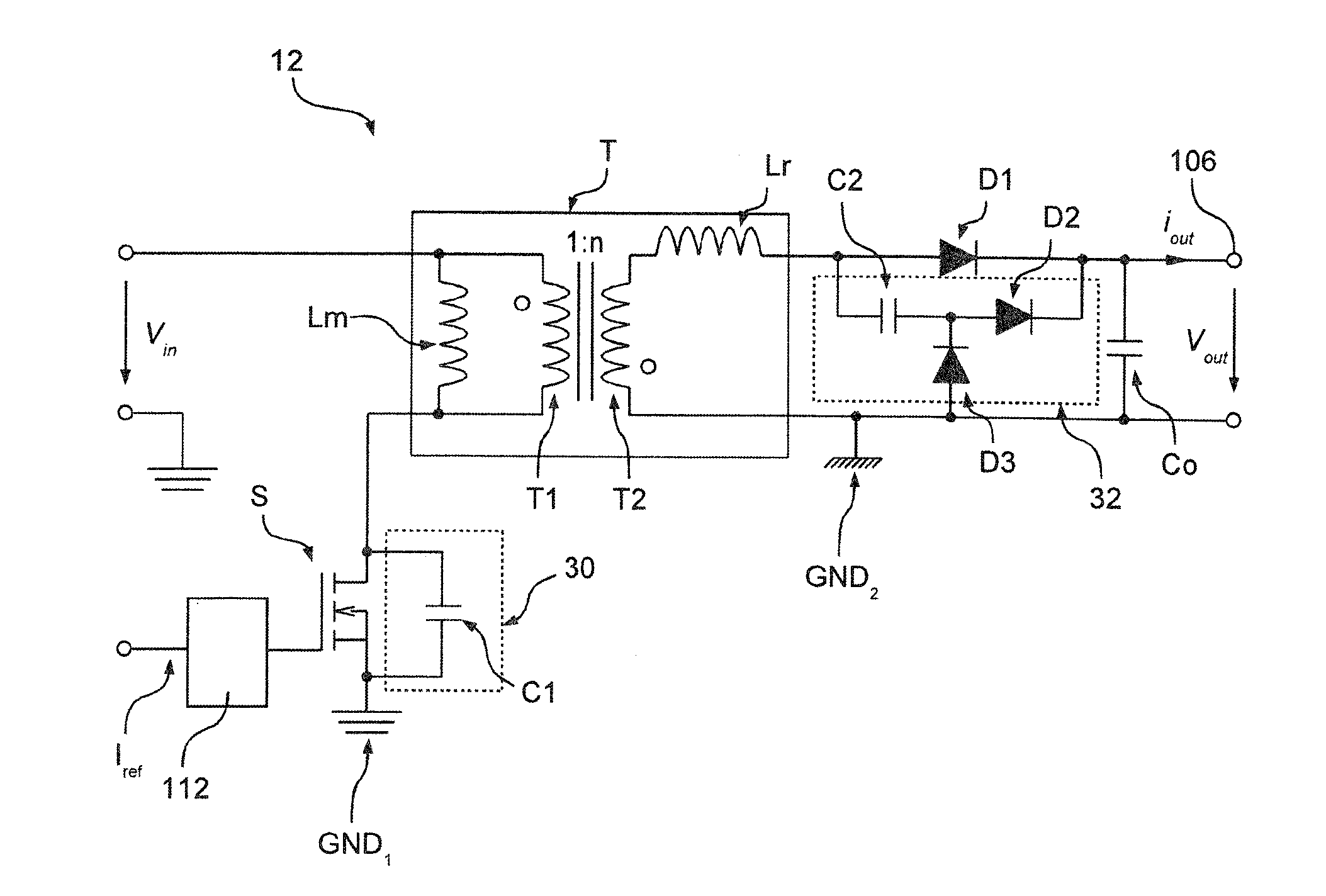
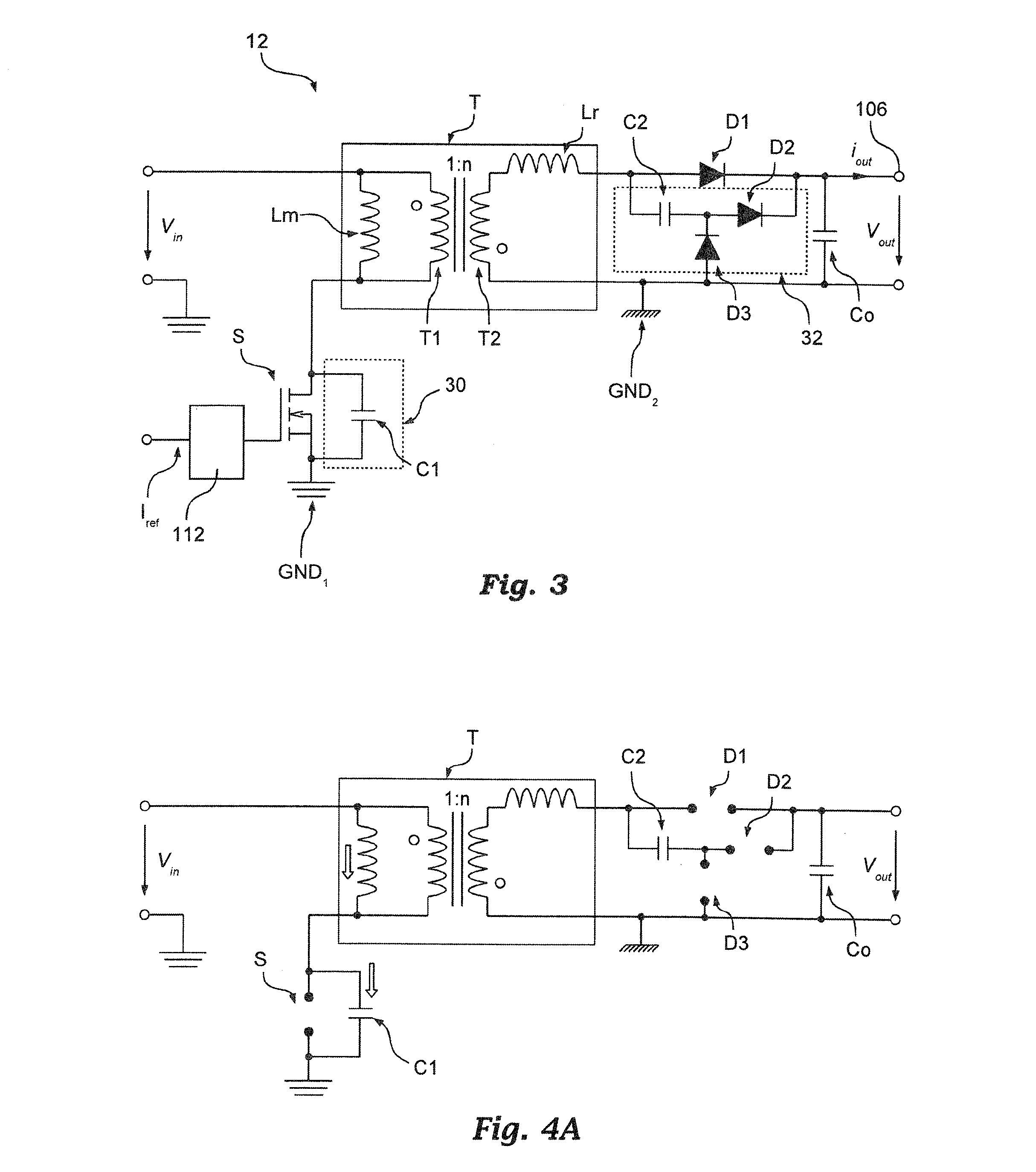
[0049]More specifically, when the primary side switch is opened, the first diode of the snubber circuit is used to discharge the capacitor of the snubber circuit and charge the capacitance associated with the primary side switch. Thus, by dimensioning in a convenient manner both capacitance values, the oscillation produced by the switch capacitance and the leakage inductance may be reduced and almost be eliminated. For example, in various embodiments, the capacitance associated with the primary side switch and the capacitor of the snubber circuit on the secondary side have similar values.

Problems solved by technology

However a flyback converter, and generally every switching power supply, comprises parasitic elements.
Actually such inductances store energy which often cannot be transferred to the load.
For example, in a flyback converter the discharge of the energy stored in the parasitic inductance Lr may cause an overvoltage across switch S. Moreover the zeroing of current through switch S cannot take place with zero voltage, which involves switching losses as well.

Method used


Image

  • Electronic converter, and related lighting system and method of operating an electronic converter
  • Electronic converter, and related lighting system and method of operating an electronic converter
  • Electronic converter, and related lighting system and method of operating an electronic converter

Examples


Embodiment Construction

[0054]In the following description, numerous specific details are given to provide a thorough understanding of embodiments. The embodiments may be practiced without one or more of the specific details, or with other methods, components, materials, etc. In other instances, well-known structures, materials, or operations are not shown or described in detail to avoid obscuring aspects of the embodiments.

[0055]Reference throughout this specification to “one embodiment” or “an embodiment” means that a particular feature, structure, or characteristic described in connection with the embodiment is included in at least one embodiment. Thus, the appearances of the phrases “in one embodiment” or “in an embodiment” in various places throughout this specification are not necessarily all referring to the same embodiment. Furthermore, the particular features, structures, or characteristics may be combined in any suitable manner in one or more embodiments.

[0056]The headings provided herein are for...


PUM


Abstract

An electronic converter may include transformer with a primary winding and a secondary winding, wherein the primary winding is coupled to an input for receiving a power signal, and wherein the secondary winding is coupled to an output including a positive terminal and a negative terminal for providing a power signal. The converter moreover may include an electronic switch arranged between the input and the primary winding, wherein the electronic switch is configured to control the current flow through the primary winding. Specifically, the converter may include a snubber circuit arranged between the secondary winding and the output.

Description

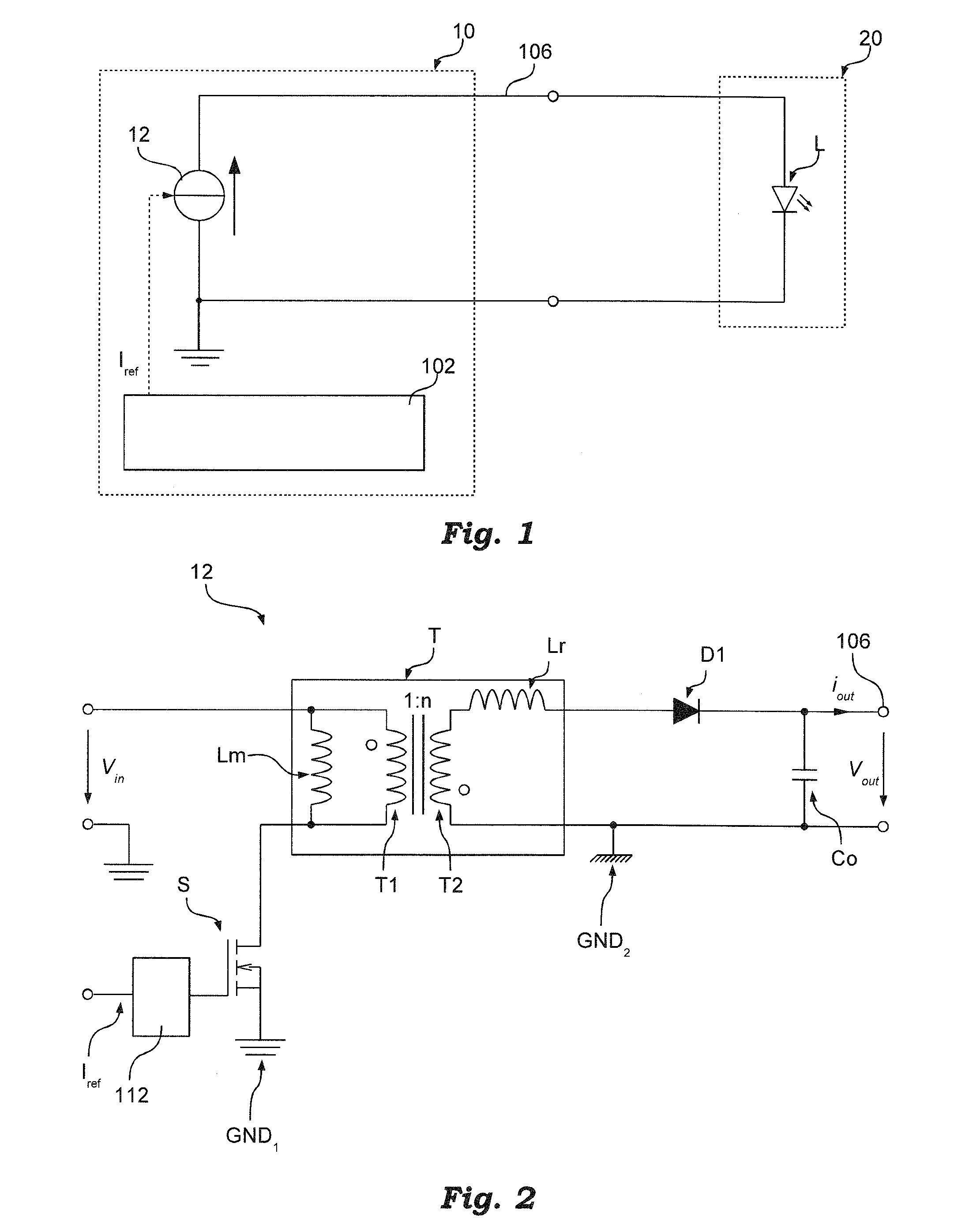
FIELD OF THE INVENTION[0001]The present disclosure relates to electronic converters.[0002]This disclosure was devised with specific attention paid to the provision of a suppressor or snubber for an electronic converter.DESCRIPTION OF THE RELATED ART[0003]Electronic converters for lighting sources comprising, for example, at least one LED (Light Emitting Diode) or other solid-state lighting means may provide a direct current output. Such current may be stable or vary in time, for example in order to regulate the light intensity emitted by the lighting source (so called dimming function).[0004]FIG. 1 shows a possible lighting system comprising an electronic converter 10 and a lighting module 20, comprising for example at least one LED L.[0005]Electronic converter 10 usually comprises a control circuit 102 and a power circuit 12 (for example an AC / DC or DC / DC switching supply) and provides as output a direct current through a power output 106. Such a current may be stable, or else may ...

Claims


Application Information

Patent Timeline
Patent Type & Authority Applications(United States)
IPC IPC(8): H02M3/335H05B44/00
CPCH02M3/33507H02M1/34H02M3/335Y02B70/10H05B45/385H02M1/346
Inventor LUCCATO, DANIELE
Owner ABL IP HLDG
Why Eureka
Try Eureka