
High-Temperature Resistant Carbon Monofluoride Batteries Having Lithiated Anode

a technology of carbon monofluoride and anode, which is applied in the direction of secondary cell servicing/maintenance, non-aqueous electrolyte cells, cell components, etc., can solve the problems of not being suited for long-term use, exposing the device to geothermal heating extremes, and military devices can be exposed to explosion-generated heat, etc., to reduce the degrading chemical reactivity, reduce the risk of explosion, and be reliable for long-term us

Inactive Publication Date: 2014-04-03
WISCONSIN ALUMNI RES FOUND
View PDF11 Cites 10 Cited by
  • Summary
  • Abstract
  • Description
  • Claims
  • Application Information

AI Technical Summary

Benefits of technology

The patent describes a new type of battery that can be charged using conventional energy sources and operate at very high temperatures. These batteries are designed to be non-rechargeable, meaning they are meant for use in applications where recharging is not necessary. The batteries are reliable and can store significant amounts of energy, making them useful in a variety of applications. Additionally, the batteries have low chemical reactivity, meaning they are less likely to cause reactions, and can operate at high temperatures. These features make the batteries ideal for use in high-temperature applications.

Problems solved by technology

While this type of prior art battery is useful for a variety of applications, it is not well suited for long term use at temperatures above 100° C. This is significant as there are various industrial and military applications for non-rechargeable batteries which would benefit if their batteries were better able to operate at higher temperatures (without significantly compromising other performance characteristics).
This can expose the device to geothermal heating extremes.
As another example, in a battlefield environment military devices can become exposed to heat generated by explosions.
Further, as bare lithium metal tends to melt at 180° C., use of such batteries above those temperatures was impractical.
However, various lithiated anodes suffered from production or reliability concerns, and in any event have not been proposed for use in ultra high temperature CFx cathode environments.

Method used


Image

  • High-Temperature Resistant Carbon Monofluoride Batteries Having Lithiated Anode
  • High-Temperature Resistant Carbon Monofluoride Batteries Having Lithiated Anode
  • High-Temperature Resistant Carbon Monofluoride Batteries Having Lithiated Anode

Examples


Embodiment Construction

[0043]Described in detail below are batteries suitable for use at highly elevated temperatures. They have an anode based on Si with lithium intercalated into this base material. It is alternatively proposed to use lithiated Si alloy anodes (e.g. lithiated Si / Sn), and / or lithiated Ge anodes, or lithiated Sn anodes.

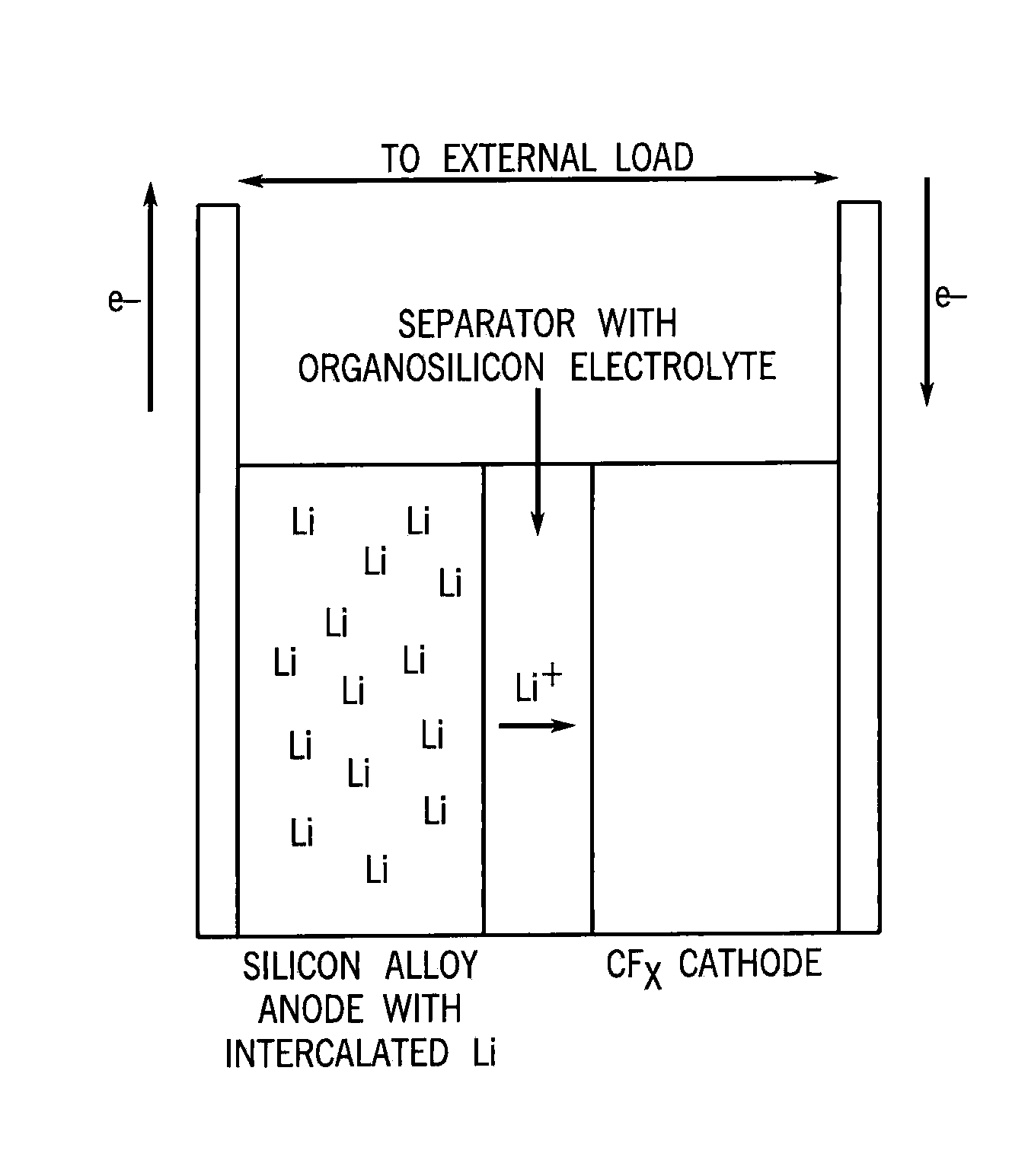
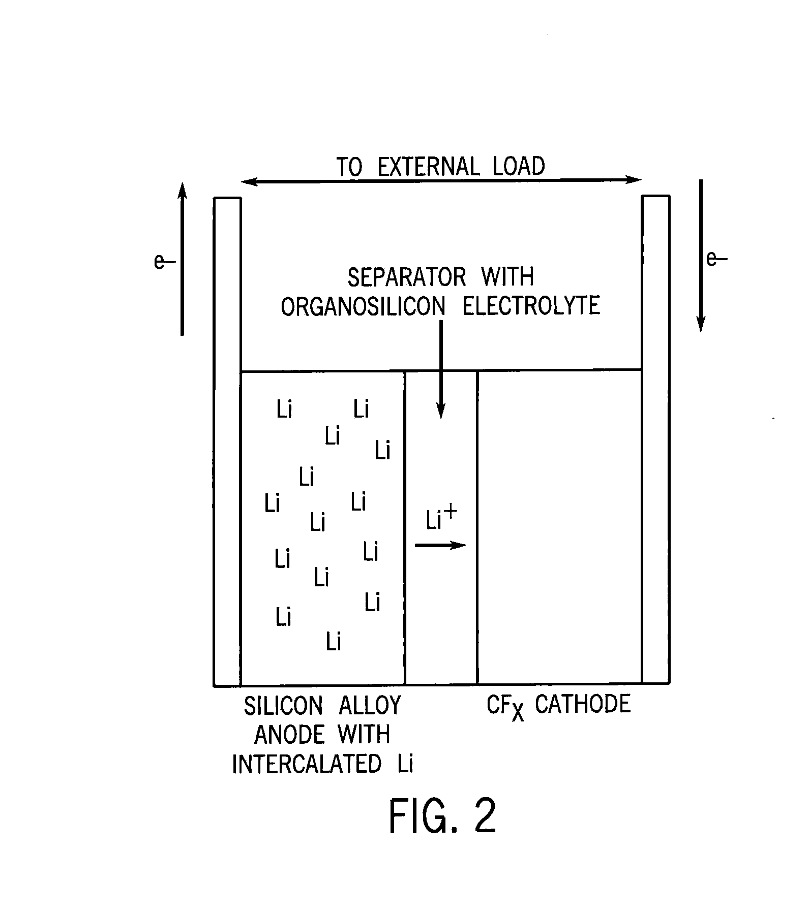
[0044]As shown in FIG. 2, a lithiated silicon anode can be coupled to a carbon monofluoride cathode, and a suitable electrolyte can be provided. On the right is the carbon monofluoride cathode, and in the center is the electrolyte that is impregnated into a “separator” that prevents physical contact of the anode and cathode while allowing Li+ ions to be transported between them via a liquid electrolyte.

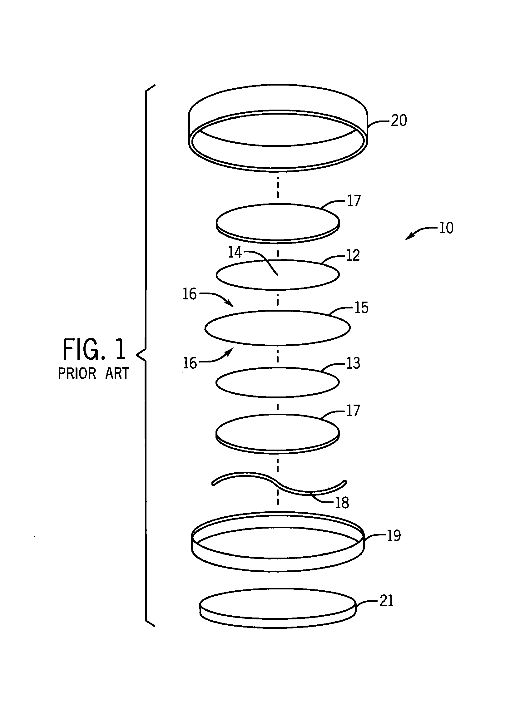
[0045]In one application of our invention a FIG. 1 type device can have its standard electrolyte replaced with a selected electrolyte solvent (e.g. tetraglyme, polypropylene carbonate, or selected high temperature resistant organosilicons are preferred). It is projected that ...


PUM


Abstract

Disclosed are carbon monofluoride cathode batteries suitable for use at highly elevated temperatures. Rather than using a pure lithium anode, the anode has a base material selected from the group consisting of silicon, germanium and tin, where the base material is lithiated. This renders the anode more resistant to heat. Selected electrolytes are used which also contain lithium salts. Methods for using these batteries at high temperatures are also disclosed.

Description

STATEMENT REGARDING FEDERALLY SPONSORED RESEARCH / DEVELOPMENT[0001]This invention was made with government support under ______ awarded by the National Science Foundation. The government has certain rights in the invention.CROSS-REFERENCE TO RELATED APPLICATIONS[0002]Not applicable.BACKGROUND OF THE INVENTION[0003]The present invention relates to lithiated anode / carbon monofluoride cathode batteries that are suitable to operate at highly elevated temperatures.[0004]In developing batteries one often seeks to achieve high voltage capability, store substantial amounts of energy, operate reliably and safely, provide energy on a timely response basis, keep the cost of the battery materials within commercially practical limits, provide a battery that operates long term without significant maintenance issues, and also keep the weight of the battery low.[0005]One type of commercially useful battery has a lithium metal anode and a carbon monofluoride cathode. “Carbon monofluoride”, which is o...

Claims


Application Information

Patent Timeline
IPC IPC(8): H01M4/38H01M6/16
CPCH01M6/162H01M4/386H01M4/5835H01M6/20
Inventor HAMERS, ROBERT J.YEAGER, JOSEPH C.
Owner WISCONSIN ALUMNI RES FOUND
Learn More