
Reduced-cross-talk coherent optical transmitter

Active Publication Date: 2019-01-15
II VI DELAWARE INC
View PDF3 Cites 3 Cited by
  • Summary
  • Abstract
  • Description
  • Claims
  • Application Information

AI Technical Summary

Benefits of technology

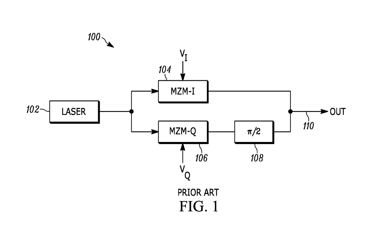
This patent text discusses the need for improved optical transmitter technology to meet the growing demand for optical fiber communication capacity. The combination of large bandwidth requirements, high port density, and lower system power consumption pushes technology limits. In-Phase Quadrature-Phase (IQ) optical modulators are important for this application as they support high modulation bandwidths. The text highlights the performance parameters needed for this application, including low drive voltage, high linearity, and high modulation bandwidth. The text also mentions the current limitations of lithium niobate-based modulators requiring larger size to achieve low drive voltages. The text concludes that compound III-V semiconductor-based modulator technologies, such as GaAs, are well-suited for this application as they have high bandwidth and compact device configurations. In particular, indium phosphide technology is compatible with low-cost packaging and can be used with wafer-scale fabrication that allows precise process controls. The cost of indium phosphide modulator components has significantly reduced using these features. The patent text also mentions the technical challenges of delivering both high modulation bandwidth and low cross talk operation for IQ modulators made from various materials.

Problems solved by technology

In addition, high-capacity systems demand a small form factor and high component reliability.
Numerous technical challenges exist for IQ modulators made from all these materials to provide both high modulation bandwidth and low cross talk operation.

Method used


Image

  • Reduced-cross-talk coherent optical transmitter
  • Reduced-cross-talk coherent optical transmitter
  • Reduced-cross-talk coherent optical transmitter

Examples


Embodiment Construction

[0012]Reference in the specification to “one embodiment” or “an embodiment” means that a particular feature, structure, or characteristic described in connection with the embodiment is included in at least one embodiment of the teaching. The appearances of the phrase “in one embodiment” in various places in the specification are not necessarily all referring to the same embodiment.

[0013]It should be understood that the individual steps of the methods of the present teachings may be performed in any order and / or simultaneously as long as the teaching remains operable. Furthermore, it should be understood that the apparatus and methods of the present teachings can include any number or all of the described embodiments as long as the teaching remains operable.

[0014]The present teaching will now be described in more detail with reference to exemplary embodiments thereof as shown in the accompanying drawings. While the present teachings are described in conjunction with various embodimen...


PUM


Abstract

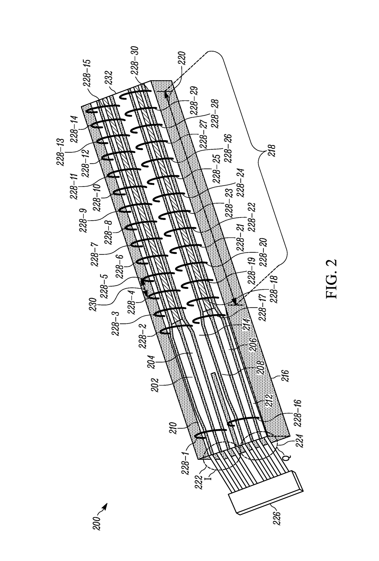
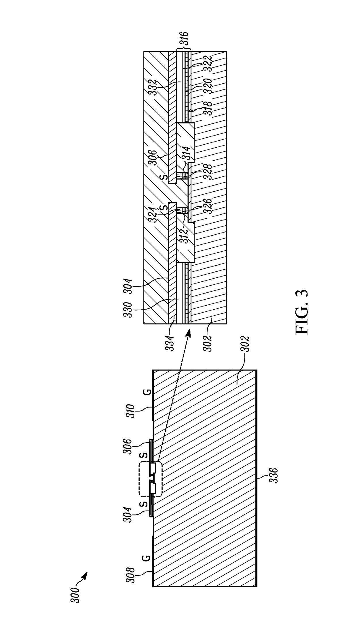
An electro-optical modulator includes a substrate comprising a first Mach-Zehnder modulator comprising a first waveguide and a second waveguide and a second Mach-Zehnder modulator comprising a first waveguide and a second waveguide. A first positive signal electrode is positioned on the substrate over the first waveguide of the first Mach-Zehnder modulator and a first negative signal electrode is positioned on the substrate over the second waveguide of the first Mach-Zehnder modulator. The first positive signal electrode and the first negative signal electrode are connected to a first differential signal input. A second positive signal electrode is positioned on the substrate over the first waveguide of the second Mach-Zehnder modulator and a second negative signal electrode positioned on the substrate over the second waveguide of the second Mach-Zehnder modulator. The second positive signal electrode and the second negative signal electrode are connected to a second differential signal input. A first ground electrode is positioned on the substrate between the first and second Mach-Zehnder modulators connected to ground potential. A second ground electrode is connected to ground potential and positioned on the substrate adjacent to the first Mach-Zehnder modulator such that the first positive signal electrode and the first negative signal electrode are between the second ground electrode and the first ground electrode. A third ground electrode is connected to ground potential and positioned on the substrate adjacent to the second Mach-Zehnder modulator such that the second positive signal electrode and the second negative signal electrode are between the third ground electrode and the first ground electrode. A plurality of first electrical connectors connect the first ground electrode to the second ground electrode and a plurality of second electrical connectors connect the first ground electrode to the third ground electrode. A spacing between at least two of the plurality of first electrical connectors is chosen to achieve a desired cross talk between an optical signal generated by the first Mach-Zehnder modulator and an optical signal generated by the second Mach-Zehnder modulator.

Description

[0001]The section headings used herein are for organizational purposes only and should not to be construed as limiting the subject matter described in the present application in any way.INTRODUCTION[0002]The ever-increasing demand for optical fiber communication capacity continues to drive improvements in optical transmitter technology used in long-haul and metro-scale optical network deployments. The need to address the combination of large bandwidth requirements, high port density, and lower system power consumption continue to push technology limits. In-Phase Quadrature-Phase (IQ) optical modulators support the high modulation bandwidths in today's coherent optical systems. Important modulator performance parameters for this application include low drive voltage to produce a phase shift of π-radians, Vπ, high linearity, high modulation bandwidth, and low insertion loss. In addition, high-capacity systems demand a small form factor and high component reliability.[0003]Current gene...

Claims


Application Information

Patent Timeline
IPC IPC(8): G02F1/025G02F1/225G02F1/03G02F1/01G02F1/21
CPCG02F1/025G02F1/2257G02F1/0316G02F1/0121G02F2001/212G02F1/212
Inventor LEWEN, ROBERTKAIKKONEN, ANDREIDAUNT, CHRISTOPHERCHACINSKI, MAREK
Owner II VI DELAWARE INC
Learn More