
Optical coherence tomography and pressure based systems and methods

a coherence tomography and optical coherence technology, applied in the field of catheters and medical diagnostics, can solve the problems of preventing the accurate ffr measurement, affecting the accuracy of ffr measurement, and presenting many challenges to clinicians, so as to reduce the non-uniform rotational distortion

Inactive Publication Date: 2014-04-03
LIGHTLAB IMAGING
View PDF11 Cites 76 Cited by
  • Summary
  • Abstract
  • Description
  • Claims
  • Application Information

AI Technical Summary

Benefits of technology

The patent relates to a torque wire assembly and a method for measuring the fractional flow reserve of a vessel. The assembly includes a protective coating and a torque wire that is coupled to an optical fiber through an interference fit. The coating is designed to reduce non-uniform rotational distortion and is a tube having an outer diameter with a spiral shape. The method involves measuring the pressure distal to a stenosis and the fractional flow reserve is determined using hydrodynamic equations and the geometric boundary of the vessel measured with the optical coherence tomography assembly. The technical effects of the invention include improving the accuracy of pressure measurements and facilitating the determination of fractional flow reserve in stenosed vessels.

Problems solved by technology

Treating vessels with stenotic lesions and other full or partial blockages present many challenges to a clinician.
Stand-alone pressure wires are usually limited to a maximum diameter of 0.014″ because larger pressure wires partially occlude the vessel in the stenotic region and cause an excessively large pressure drop.
This large pressure drop prevents obtaining an accurate FFR measurement.
The combination of a torque wire and an OCT probe would typically disturb any pressure measurement made with the OCT probe placed across a lesion in the vessel.

Method used


Image

  • Optical coherence tomography and pressure based systems and methods
  • Optical coherence tomography and pressure based systems and methods
  • Optical coherence tomography and pressure based systems and methods

Examples


Embodiment Construction

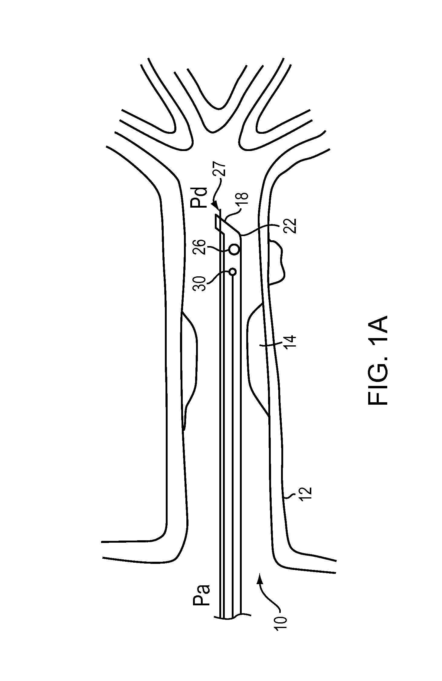
[0085]U.S. patent application having Publication No. 2011-0071404 assigned to the owner of this application and herein incorporated by reference in its entirety describes a method of calculating a pressure drop in a lumen and related methods of obtaining FFR (fractional flow reserve). A data collection probe, such as an OCT probe, a pressure data probe or other probes suitable for collecting data used to measure or determine FFR or related parameters can be used as described herein. In one embodiment, when collecting data with respect to a blood vessel, the data collection probe is disposed in the lumen of the vessel.

[0086]In brief overview, one method for calculating a pressure drop in a lumen and measuring a fractional flow reserve (FFR) requires that the pressures measured within the vessel distal to a stenotic region be corrected for the effect of the probe partially obstructing flow through a stenotic region. To do this, an OCT image is made of the stenosis; an estimate of the ...


PUM


Abstract

In part, the invention relates to methods, apparatus, and systems suitable for determining a fractional flow reserve (FFR) and variations of modifications thereof One embodiment relates to a method and apparatus for obtaining a corrected FFR in a vessel having a stenosis. In one aspect, the invention relates to an apparatus for measuring corrected FFR of a vessel having a stenosis. In one embodiment, the apparatus includes a probe comprising an optical coherence tomography assembly and a pressure assembly; and a processor in communication with the optical coherence tomography assembly and the pressure assembly. In one embodiment, the pressure assembly measures values of pressure in predetermined locations the vessel and communicates them to the processor. In one embodiment, a dual guidewire is used to reduce the interference in the pressure measurement.

Description

RELATED APPLICATIONS[0001]This application claims the benefit of and priority to U.S. Provisional application 61 / 490,925 filed May 27, 2011 and U.S. Provisional application 61 / 529,594 filed Aug. 31, 2011, the entire disclosures of each of which are herein incorporated by reference.FIELD OF THE INVENTION[0002]In part, the invention relates generally to the field of catheters and medical diagnostics and more specifically to the field of intra-lumen pressure measurement and imaging devices.BACKGROUND[0003]Treating vessels with stenotic lesions and other full or partial blockages present many challenges to a clinician. Determining the amount of flow through a narrowed or stenotic region of a blood vessel helps a clinician evaluate the severity of the obstruction and select a treatment. Pressure wires inserted into the vessel at locations before and after the stenosis detect pressure values that can be used to ascertain blood flow through the artery. The values can be used to inform a tr...

Claims


Application Information

Patent Timeline
IPC IPC(8): A61B5/00A61B1/015A61B5/026A61B5/02A61B5/0215A61B1/07
CPCA61B5/0066A61B2576/023A61B5/6852A61B5/6876A61B5/0084A61B5/1076A61B5/1077A61B2562/0233A61B2562/0247A61B5/7278A61B5/026A61B5/02158A61B5/02028A61B1/07A61B1/015A61B5/7282A61B5/0215
Inventor PETROFF, CHRISTOPHERSCHMITT, JOSEPH
Owner LIGHTLAB IMAGING
Learn More